10
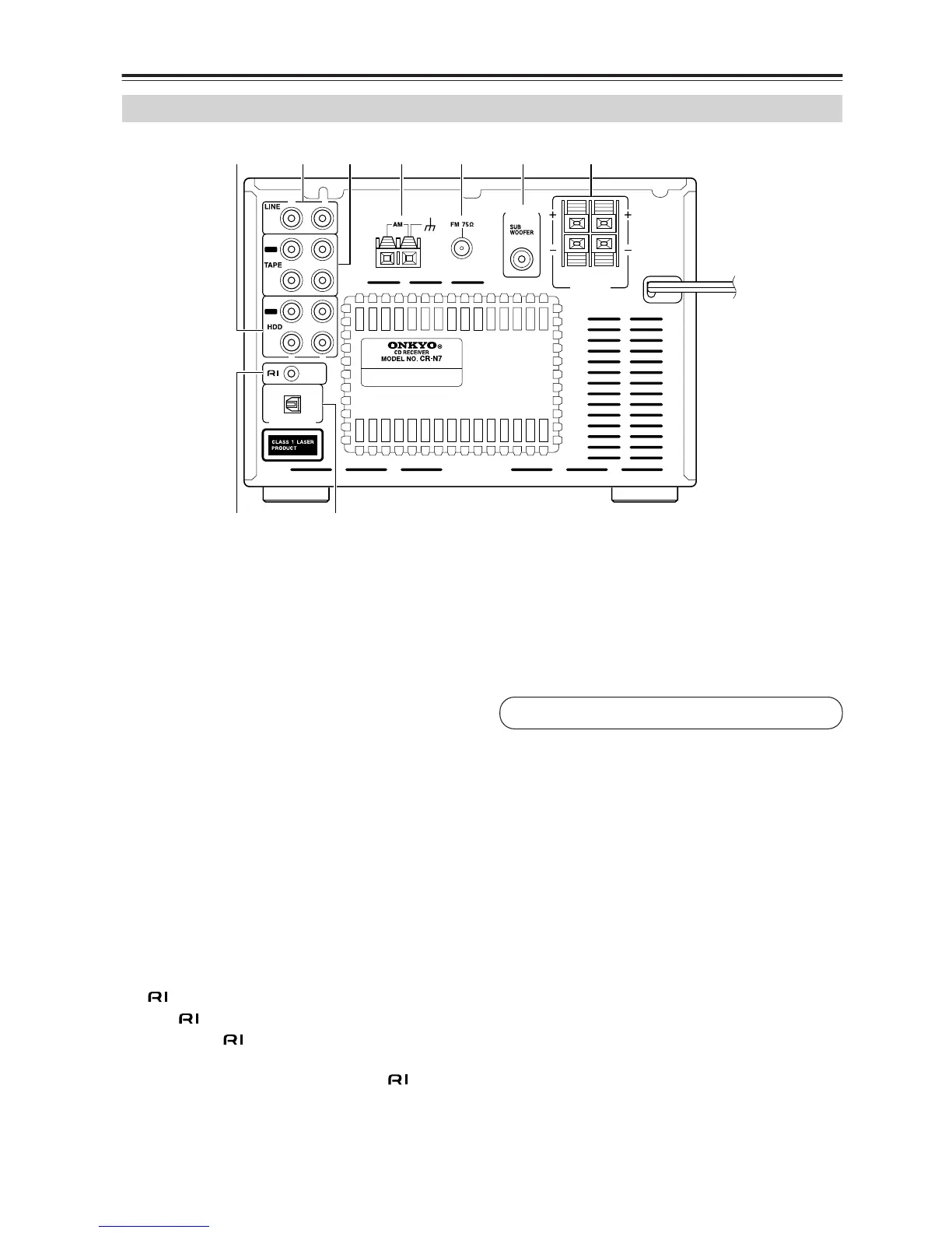
Part Names and Functions—Continued
The page numbers in parentheses show where you can find the main explanation for each item.
A HDD IN/OUT (19)
Here you can connect an RI Dock or a CD recorder.
B LINE IN (18)
These terminals are for connecting audio output of
external devices such as TV or turntable with a
built-in phono equalizer.
C TAPE IN/OUT (18)
This analog audio input and output are for connect-
ing a recorder with an analog audio input and output
(cassette, Mini Disc, etc.).
D AM ANTENNA (14, 15)
These push terminals are for connecting an AM
antenna.
E FM ANTENNA (14, 15)
This jack is for connecting an FM antenna.
F PRE OUT (17)
The SUBWOOFER jack is for connecting a pow-
ered subwoofer.
G SPEAKERS (16)
These terminals are for connecting speakers.
H REMOTE CONTROL (18-20)
This (Remote Interactive) jack can be con-
nected to an jack on another Onkyo component.
The CD receiver’s remote controller can then be
used to control that component. To use , you
must make an analog audio connection (RCA)
between the CD receiver and the other component,
even if they are connected digitally.
I OPTICAL DIGITAL OUT (20)
The optical output can be used to connect a CD
recorder or other digital recorder with an optical
digital input. The CD receiver’s CD signal is output
through this terminal.
Rear Panel
CAUTION:
SPEAKER IMPEDANCE
4
OHMS MIN. /SPEAKER
SPEAKERS
PRE
OUT
R
L
REMOTE
CONTROL
OPTICAL
IN
OUT
IN
IN
OUT
R
L
R L
DIGITAL OUT
ANTENNA
G
1BCD 65
9H
See pages 14-20 for connection information.
 Loading...