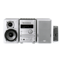
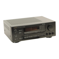
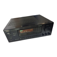
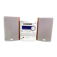
FR-N3X
1
6-1
6-2
6-3
6-4
6-6
6-7
LEADER
LEADER
LE8010
LP-8010-02
A-BEX
0J12
0F001
0J16
---
---
---
ADJUSTMENT PROCEDURES-1
MD ADJUSTMENT
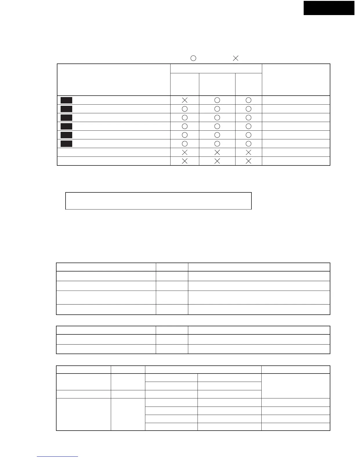
1.Necessity for adjustment
unnecessarynecessary
Exchanged parts
Pickup unit
Parts on MD
mount,
and Motors
Mechanical
parts
Adjustment of Temperature Compensation Offset
Adjustment of laser power
Check of laser power
Adjustment of Traverse (EF balance)
Check of error rate in high reflectance disk
Check of error rate in low reflectance disk
Adjustment of focus Bias
Check of focus bias
2. Notes in adjustment
2-1. Laser of optical pickup
2-2. Perform adjustment using test mode.
2-3. Perform adjustment as the indicated turn.
2-4. After adjustment should cancel test mode.
3. Equipment
Digital volt meter
Oscilloscope
Optical sensor
Laser power meter
Frequency range is 40MHz or more.
The calibration of the probe is performed.
In case adjust, don't look at the laser of the pickup unit.
You have fear of loss of eyesight.
Name
Name
Name
3-1. Measuring instruments
3-2. Test disks
Description and remarks
DetailsPart No.
Manufactured
Standard disk for recording/play back
FFC socket
PC board
Flexible flat cable
Extended JIG
1mm pitch, 7 cores
Part No. NCJIG-0J12
Part No. 25052307
---
Part No. NCJIG0J16
Part No. 25051759A
Part No. 25052313
Part No. 2045131012
Adjustment item
Manufactured
MO disk
High reflectance disk
3-3. JIGs
Description and remarks
Remarks
Black
Gray
PC board
FFC socket, 7 cores
FFC socket, 13 cores
Flexible flat cable (13cores)
TDM-381 Test disc
Extended JIG
 Loading...