EasyManua.ls Logo

Onkyo HTR-990 - User Manual

Onkyo HTR-990
115 pages
Print Icon
To Next Page IconTo Next Page
Loading...
HT-R990
RC-801M
North American models ---> “DIMMER”
European models ---> “RT/TPY/TP”
AV RECEIVER
MODEL
HT-R990(B)
Ref. No. 4285
052011
HT-R990 for HT-S9400THX Black model
120V AC, 60HzB MDC
HT-R990 for HT-S9405THX Black model
230V AC, 50HzB MPP
Question and Answer IconNeed help?

Do you have a question about the Onkyo HTR-990 and is the answer not in the manual?

Onkyo HTR-990 Specifications

General IconGeneral
BrandOnkyo
ModelHTR-990
CategoryReceiver
LanguageEnglish

Summary

ONKYO SERVICE MANUAL

AV Receiver Model HT-R990(B)

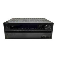
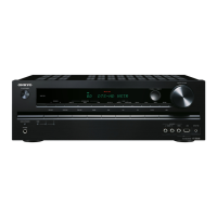
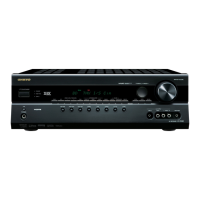
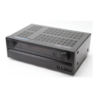
Identifies the specific AV receiver model covered in the manual.

SAFETY-RELATED COMPONENT WARNING!

Critical Component Identification

Highlights critical components requiring caution due to fire/shock risk.

SCHEMATIC DIAGRAM;BLOCK DIAGRAM-1

Audio Section Block Diagram

Provides a block-level view of the audio processing and amplification circuitry.

SCHEMATIC DIAGRAM;BLOCK DIAGRAM-2

Video Section Block Diagram

Illustrates the signal flow for video processing and input/output.

SCHEMATIC DIAGRAM;BLOCK DIAGRAM-3

Audio Input Section Parts

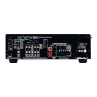
Details the components and connections for various audio input sources.

SCHEMATIC DIAGRAM;BLOCK DIAGRAM-4

Amplifier Section

Outlines the structure and components of the power amplifier section.

SCHEMATIC DIAGRAM;BLOCK DIAGRAM-6

Digital Input, DAC, and MPU Section

Covers the digital audio processing, DAC, and microprocessor sections.

SCHEMATIC DIAGRAM;BLOCK DIAGRAM-7

Video Section

Details the video processing, input/output, and related circuitry.

SCHEMATIC DIAGRAM;BLOCK DIAGRAM-9

SCHEMATIC DIAGRAM;BLOCK DIAGRAM-10

Power Supply Section

Details the power supply circuitry, including fuses and transformers.

SCHEMATIC DIAGRAM-14

VMPU;Power Section

Covers the VMPU and power distribution circuitry.

SCHEMATIC DIAGRAM;BLOCK DIAGRAM-15

HDMI Input Switch Section

Details the circuitry for switching between multiple HDMI input sources.

SCHEMATIC DIAGRAM;BLOCK DIAGRAM-16

HDMI Section

Covers the HDMI interface and related signal processing components.

SCHEMATIC DIAGRAM;BLOCK DIAGRAM-17

Video Processor Section

Details the function and components of the video processing unit.

SCHEMATIC DIAGRAM;BLOCK DIAGRAM-18

DSP Audio Section

Outlines the digital signal processing and audio circuitry.

SCHEMATIC DIAGRAM;BLOCK DIAGRAM-19

SCHEMATIC DIAGRAM;BLOCK DIAGRAM-20

EXPLODED VIEW PARTS LIST

Related product manuals