39
Connecting Components not Reached by the Remote
Controller Signals (IR IN/OUT)
In order to use the remote controller to control the
receiver from a remote location, you will need to
prepare a multiroom kit (sold separately) such as one
listed below:
• Multiroom A/V distribution and control system such
as those from Niles
®
and Xantech
®
* Xantech is a registered trademark of Xantech Corporation.
* Niles is a registered trademark of Niles Audio Corporation.
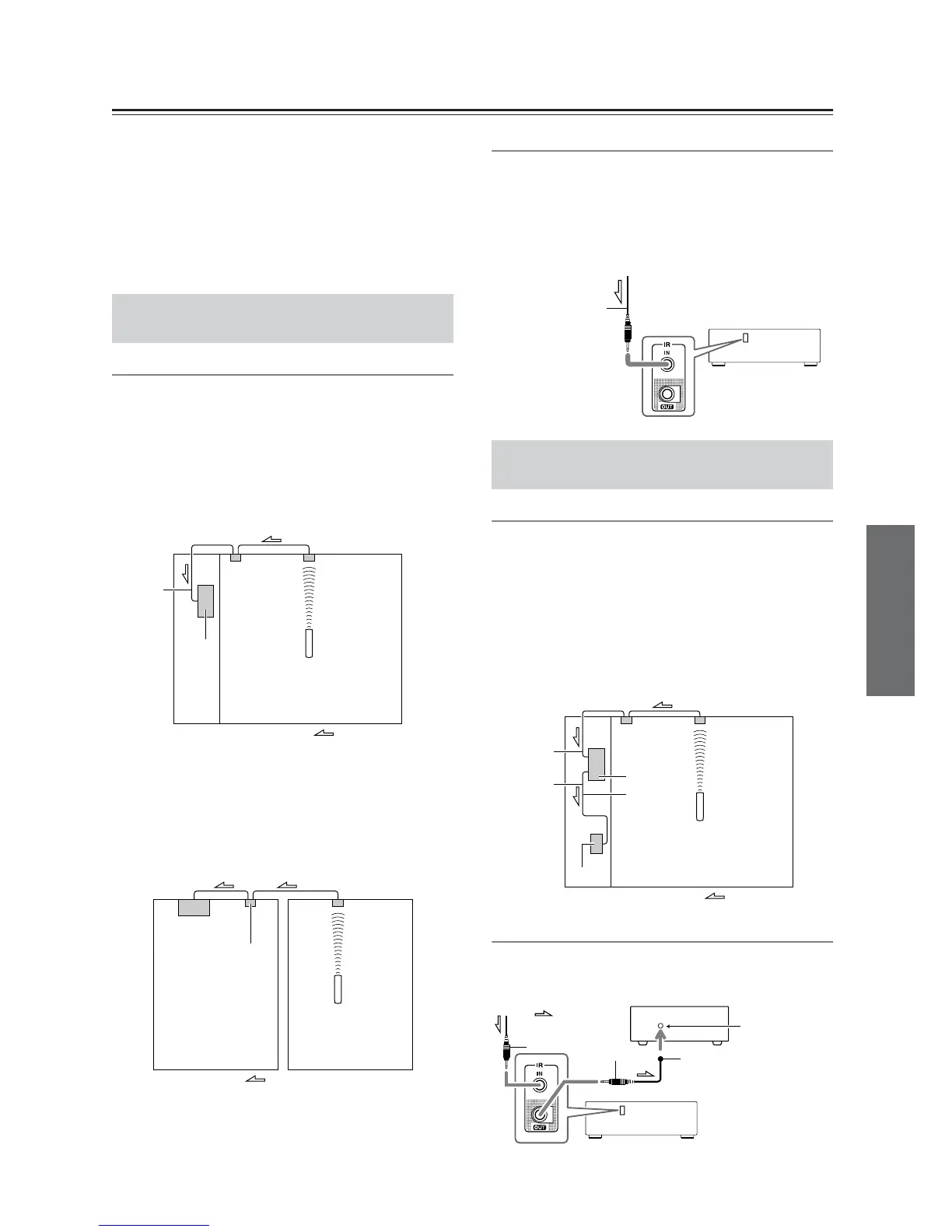
Effective Sensor Layout
Example for the main room
If the receiver is located inside a cabinet or other
enclosure where the infrared rays from the remote
controller cannot enter, then operation with the remote
controller will not be possible. In such a case, it will be
necessary to install a remote sensor at a location outside
of the cabinet so that the infrared rays from the controller
can be sensed.
Example for Zone 2
The IR IN input allows you to control the receiver from
Zone 2 with the remote controller even though Zone 2
may be on the other side of the building from the main
zone. The diagram below shows how to make the proper
connections for Zone 2.
Making Sensor Connections
When you place the IR receiver in the main room, connect
the cable from the connecting block to the IR IN terminal.
Make the connection as shown below. Do not plug any
equipment into the power outlet until all the connections
are complete.
Effective Sensor Layout
In this situation, you will need to use a commercially
available IR emitter. Connect the mini plug of the IR
emitter to the IR OUT terminal on the receiver and then
place the IR emitter on the remote sensor of the
component or facing it. When the IR emitter is
connected, only the signal input to the IR IN terminal is
output to the IR OUT terminal. The signal input from the
remote sensor on the front of the receiver will not be
output to the IR OUT terminal.
Making Sensor Connections
The IR emitter should be connected to the receiver’s IR
OUT Terminal, as shown below.
If Remote Controller Signal Does not
Reach the Receiver Remote Sensor
Connecting
block
IR Receiver
Remote controller
IR IN
Receiver
In the
cabinet
: Signal flow
Main room
IR Receiver
Remote controller
Connecting
block
Receiver
Main room
Zone 2
: Signal flow
To IR IN
If Remote Controller Signal Does not
Reach Other Components
Receiver
from connecting block
Mini plug cable
IR Receiver
Remote controller
Connecting
block
IR IN
IR OUT
IR Emitter
Receiver
Other
component
: Signal flow
: Signal flow
Other component
Emitter
Remote control
sensor
IR Emitter
Mini plug
Receiver
Mini plug
 Loading...