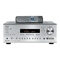
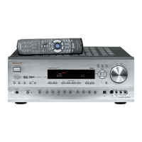
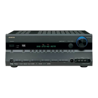
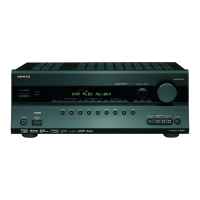
TX-SR702/E
MICROPROCESSOR-TERMINAL DESCRIPTIONS
No. Terminal Symbol I/O Act. Description
65 P47/~CS3 VLTNSTB O H Strobe signal output terminal for selector, volume and tone control IC.
66 P46/~CS2 VLTNCLK O CLK Clock output terminal for selector, volume and tone control IC.
67 P45/~CS1 VLTNDAT O H Data output terminal for selector, volume and tone control IC.
68 P44/~CS0 PLLCE O H Chip enable out terminal for tuner unit
69 P43/A19 PLLSDO O H Data output terminal for tuner unit
70 P42/A18 ~PLLSDI I L Data input terminal from tuner unit
71 P41/A17 PLLCLK O CLK Clock output terminal for tuner unit
72 P40/A16 ~STEREO I L Stereo detection input terminal from tuner unit
73 P37/A15 ~SD I L broadcast detection input terminal from tuner unit
74 P36/A14 TUMUT O H Mute control output terminal for tuner unit
75 P35/A13 AMUT O H Muting control output terminal of audio section
76 P34/A12 APOWER O H Power supply relay control output terminal
77 P33/A11 SPRLF O H Speaker relay control output terminal of front channel
78 P32/A10 SPRLCS O H Speaker relay control output terminal of center and surround channels
79 P31/A09 SPRLZ2 O H Speaker relay control output terminal of zone 2
80 P124 SPRLSB O H Speaker relay control output terminal of surround back channel
81 P123 Z2LPMUT O H Muting control output terminal of zone 2 and pre output terminal
82 P122 SBZ2MUT O H Muting control output terminal of zone 2 and surround back channels.
83 P121 ~FANCTR O L Lower speed or off setting output terminal of fun
84 P120 ~FANH O L High speed setting output terminal of fun
85 Vcc2 Vcc2 I Connect to 2.7V<Vcc2
㻡
Vcc1<5.5V
86 P30/A8(/-/D7) VPOWER O H Power supply control output terminal of video section
87 Vss Vss I Connect to ground terminal
88 P27/AN27/A7(/D7/D6) INIT7 I A/D Initializing terminal
89 P26/AN26/A6(/D6/D5) INIT6 I A/D Initializing terminal
90 P25/AN25/A5(/D5/D4) INIT5 I A/D Initializing terminal
91 P24/AN24/A4(/D4/D3) INIT4 I A/D Initializing terminal
92 P23/AN23/A3(/D3/D2) INIT3 I A/D Initializing terminal
93 P22/AN22/A2(/D2/D1) INIT2 I A/D Initializing terminal
94 P21/AN21/A1(/D1/D0) INIT1 I A/D Initializing terminal
95 P20/AN20/A0(/D0/-) BAND I A/D Band area setting input terminals of tuner section
96 P17/D15/~INT5 SYSIN I H RI input terminal
97 P16/D14/~INT4 ~IRIN I L IOR IN input terminal
98 P15/D13/~INT3 ~RDSCLK I L [MPP]RDS IC clock input terminal
99 P14/D12 RDSDAT I L RDS IC data input terminal
100 P13/D11 RDSSIG I L RDS IC demodulator signal input terminal
101 P12/D10 ~SYSOUT O H RI output terminal
102 P11/D9 THERMAL I H Thermal detection input terminal
103 P10/D8 PROTECT I H Voltage protect input terminal
104 P07/AN07/D7 SEC1H O H Power amplifier voltage select terminal
105 P06/AN06/D6 VOLH I A/D Power amplifier voltage detection input terminal
106 P05/AN05/D5 DSPBUSY I H DSP BUSY signal detection terminal
107 P04/AN04/D4 ~MICDET I L Microphone signal detection input terminal
108 P03/AN03/D3 ~HPDET I L Headphone detection input terminal
109 P02/AN02/D2 HPRL O H Headphone relay control output terminal
110 P01/AN01/D1 VJA I H Rotary encoder input terminal for volume
111 P00/AN00/D0 VJB I H Rotary encoder input terminal for volume
112 P117 LEDSTBY O L STANDBY/RECV indicator control output terminal
113 P116 LEDPURE O H PURE AUDIO indicator control output terminal
114 P115 LEDZ2 O H ZONE2 indicator control; output terminal
115 P114 LEDVOL O H VOLUME control output terminal
116 P113 ~VMUT O L Muting control output terminal of video section
117 P112 12VTRGA O H 12V Trigger A control output terminal
118 P111 12VTRGB O H 12V Trigger B control output terminal
119 P110 12VTRGC O H 12V Trigger C/Z2 control output terminal
120 P107/AN7/~KI3 ~KI3 I L Key input interrupter input terminal
121 P106/AN6/~KI2 ~KI2 I L Key input interrupter input terminal
122 P105/AN5/~KI1 ~KI1 I L Key input interrupter input terminal
123 P104/AN4/~KI0 ~KI0 I L Key input interrupter input terminal
124 P103/AN3 K3 I A/D Key input terminal
125 P102/AN2 K2 I A/D Key input terminal
126 P101/AN1 K1 I A/D Key input terminal
127 AVss AVss I Connect to Vss. Power supply terminal for A/D converter.
128 P100/AN0 K0 I A/D Key input terminal
 Loading...