Do you have a question about the Onkyo TX-SR875 and is the answer not in the manual?
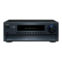
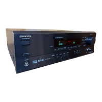
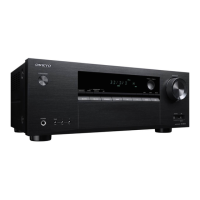
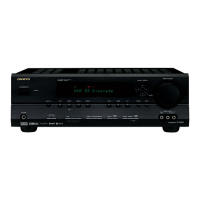
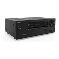
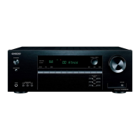
Identifies the specific model of the AV Receiver covered by the manual.
Critical safety warning about components related to fire and electric shock risks.
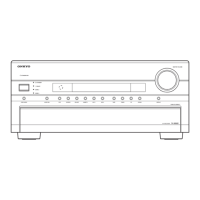
Provides a visual breakdown of the AV Receiver's external and internal components.
Continues the visual breakdown of the AV Receiver's components.
Illustrates the signal flow and component interactions within the audio processing section.
Depicts the signal path for video inputs and outputs, including component and composite signals.
Outlines the signal flow and processing for the HDMI input and output interfaces.
Detailed schematic of the audio section, showing component interconnections and signal paths.
Details the power supply circuitry, including voltage regulation and distribution.
Illustrates the block diagram and connections of the main microprocessor.
Shows the block diagram and connections for the Digital Signal Processor (DSP) units.
Shows the component layout of the Amplifier PC Board (NAASP-9050) from Side-A.
Displays the component layout of the Power Supply PC Board (NAPS-9040) from the component side.
Shows the component layout of the Amplifier PC Board (NAASP-9050) from Side-A.
Displays the component layout of the Video PC Board (NAVD-9052) from Side-A.
Shows the component layout of the Speaker Terminal PC Board (NATRM-9055) from the component side.
Displays the component layout of the Speaker Terminal PC Board (NAETC-9056) from the component side.
Shows the component layout of the Power Supply PC Board (NAPS-9057) from the component side.
Shows the component layout of the Power Amp PC Board (NAAMP-9061) from the component side.
Outlines service procedures, starting with fuse replacement and unit initialization.
Details service procedures, focusing on power amplifier parts replacement.
Explains how to check the firmware versions of Main, DSP, HDMI, and Video components.
Details preparation and connection for updating the Main microprocessor firmware.
Details preparation and procedure for updating the HDMI firmware.
Details preparation and procedure for updating the DSP firmware.
Describes checking speaker protection status related to DC voltage detection.
Details checking speaker protection status related to current detection.
Explains checks for power supply control, including output sensors and thermal sensors.
Outlines conditions that trigger the unit's protect mode and fan operation.
Explains how to access Debug Mode for checking DSP and DIR operations.
Continues Debug Mode explanation, focusing on troubleshooting common issues.
Explains how to interpret service information displayed in debug mode.
Outlines the procedure for adjusting the idling current.
Provides a second procedure for adjusting idling current, including specific test points.
Shows layouts for specific amplifier boards for adjustment.
Shows layouts for additional amplifier boards for adjustment.
A list of parts with their reference numbers, descriptions, quantities, and part numbers.
Important notes regarding parts marked with 'NSP' and 'NRP' for replacement.
Block diagram and terminal descriptions for the R2S15211FP IC.
Block diagram for the CS3318 IC, managing 8-channel analog volume control.
Block diagram and pin configuration for the CS42516 audio codec IC.
Block diagram and pin configuration for the PCM1796DBR DAC IC.
Explains how to check the firmware versions of Main, DSP, HDMI, and Video.
Details preparation and connection steps for updating the Main microprocessor firmware.
Details preparation and procedure for updating the HDMI firmware.
Details preparation and procedure for updating the DSP firmware.
Explains how to access Debug Mode for checking DSP and DIR operations.
Continues Debug Mode explanation, focusing on troubleshooting common issues.
Outlines service procedures, starting with fuse replacement and unit initialization.
Details service procedures, focusing on power amplifier parts replacement.
Outlines the procedure for adjusting the idling current.
Provides a second procedure for adjusting idling current, including test points.
Shows layouts for specific amplifier boards for adjustment.
Shows layouts for additional amplifier boards for adjustment.
Provides contact information for the Onkyo Corporation.
Lists contact details for the Onkyo U.S.A. Corporation.
Provides contact information for Onkyo Europe Electronics GmbH.
Lists contact details for the Onkyo Europe UK Office.
| Type | AV Receiver |
|---|---|
| Amplifier Type | Discrete |
| Number of channels | 7.1 |
| Frequency Response | 5 Hz - 100 kHz |
| Input Sensitivity | 200 mV |
| Total Harmonic Distortion | 0.05% |
| Signal-to-Noise Ratio | 110dB |
| HDMI Inputs | 4 |
| HDMI Outputs | 2 |
| Video Inputs | Component: 3, S-Video: 4 |
| Audio Inputs | 6 |
| Audio Formats Supported | Dolby TrueHD, DTS-HD Master Audio |
| THX Certified | Yes |
| Dimensions | 17.1 x 8.1 x 18.8 inches |