V1.1-ENG
1 www.onlab.com.tr
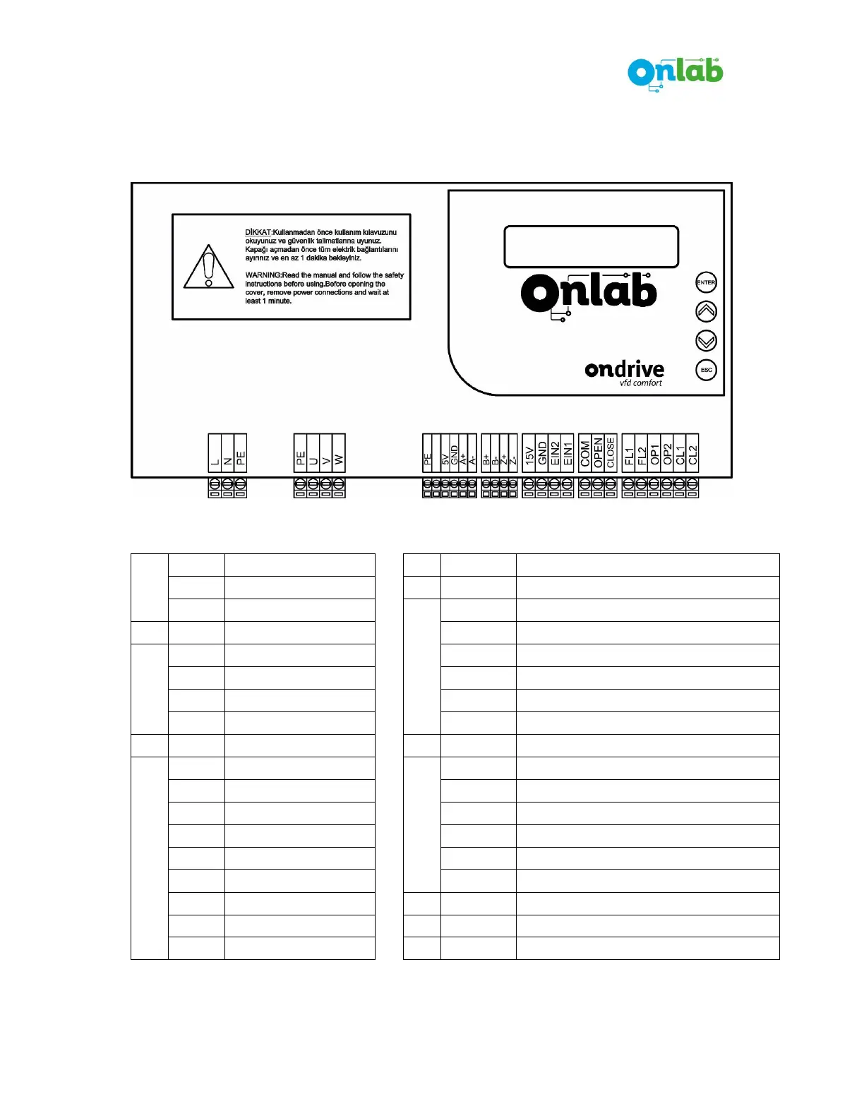
GENERAL VIEW
GRID
L: 220Vac Line 15V: 15V supply (+) terminal for input signals
N: 220V AC Neutral GND 15V supply (-) terminal for input signals
PE: Earth
INPUT
EIN2: Programmable input 2
EIN1: Programmable input 1
MOTOR
PE: Earth
U: U Phase COM: Common terminal for open/close signals
V: V Phase OPEN: Open signal input
W: W Phase CLOSE: Close signal input
ENCODER
PE: Earth
OUTPUT
FL1: Common terminal of fault relay
5V: (+) supply for encoder
FL2: NO terminal of fault relay
GND: (-) supply for encoder
OP1: Common terminal of “door opened” relay
A+: A+ channel of encoder
OP2: NO terminal of “door opened” relay
A-: A- channel of encoder
CL1: Common terminal of “door closed” relay
B+: B+ channel of encoder
CL2: NO terminal of “door closed” relay
B-: B- channel of encoder
Z+: Z+ channel of encoder
Z-: Z- channel of encoder
*Mechanical dimensions of the product are given in another document on Onlab website.
Connector Descriptions