12
USE AND MAINTENANCE INSTRUCTIONS
MANUALE DI USO E MANUTENZIONE
ã Installation gangway mod.3800
n Make the hydraulic connections to the hydraulic unit and the
electric connections of the solenoid valves and the digital
panel to the electronic box.
n Power the electronic to the battery of the boat with the
supplied electric cable or eventually with another extension cable.
n Power the electric motor with cable with suitable section by a
fuse (material non supplied standard by Opacmare), checking
the correct tension. (See pag. 8).
n Lift up the pantograph of the gangway pushing the button on
the digital panel.
n Lift up the gangway, at least in two persons, and insert the
gangway in the assigned compartment.
n Make the fixing holes on the resine and if it is necessary insert
some thickness between the plates of fixing and the resine on
the boat.
n Fix to the compartment the anchor plates with AISI 316
stainless screws M10 and seal around the edges with silicone
filler.
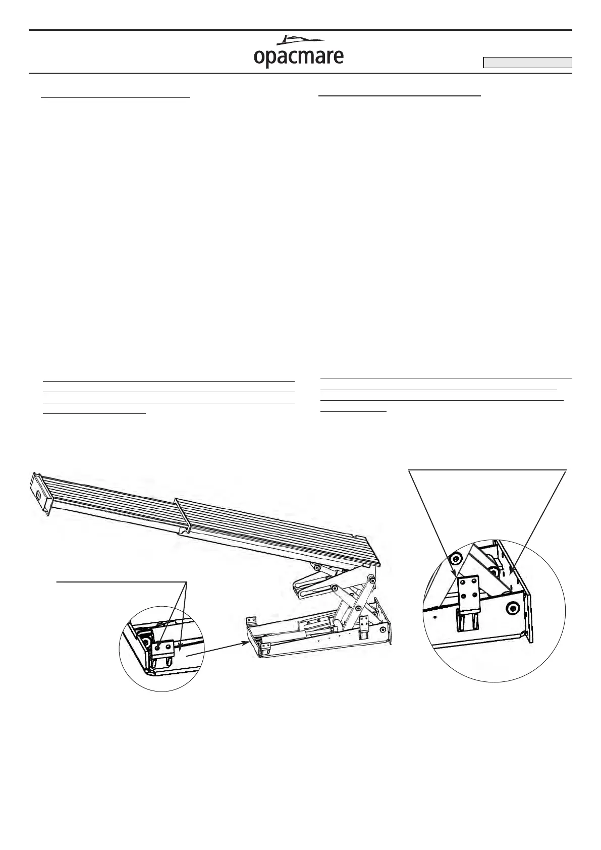
n Carry out the fixing as indicated in the picture.
n Check that the tank of the hydraulic unit is correctly filled with
fluid, and connected to electrical power. Flush the lifting
cylinder making 3 or 4 operation cycles.
n Top up the tank of the hydraulic unit if necessary.
Check that the hydraulic circuits have no leaks.
n After you have fixed the gangway, during the moving check
phase; check that the flexible hydraulic pipes, that are
located in the lower part of the gangway, are not crushed
during the closing phase.
Picture 7: Installation gangway mod. 3800 / Fig. 7: Installazione passerella mod. 3800
Side fixing holes for M10
screws
Fori per il fissaggio laterale
usare viti M10
Fixing holes for M10
screws
Fori per il fissaggio
usare viti M10
On the hydraulic unit there is a flow regulation valve that has been
correctly set by OPACMARE before delivery of your gangway.
Sulla centralina oleodinamica sono montate delle valvole regolatri-
ci di flusso (tarate da OPACMARE in fase di collaudo) che hanno
la funzione di frenare la discesa della passerella.
Transom gangway
Passerella esterna
EDITION OF 08/2008
ã Installazione passerella mod.3800
n Effettuare i collegamenti idraulici alla centralina idraulica e
quelli elettrici delle elettrovalvole e della pulsantiera con il box
elettronico.
n Alimentare l’elettronica alla batteria dell’imbarcazione con il
cavo elettrico in dotazione ed eventualmente prolunghe
aggiuntive.
n Alimentare il motore elettrico con cavi di sezione appropriata
attraverso un fusibile (materiale non fornito standard
dall’OPACMARE), controllando la corretta tensione.
(Vedi tabella pagina 8).
n Sollevare il pantografo della passerella premendo il tasto sulla
pulsantiera.
n Sollevare la passerella, almeno in due persone, e inserirla nel
vano stabilito.
n
Praticare i fori di fissaggio sulla resina e se necessario inserire
degli spessori tra le piastre di fissaggio e la resina dell’imbarcazione
n Fissare al vano le piastre di ancoraggio mediante viti inox AISI
316 M10
sigillandone il perimetro con silicone.
n Effettuare i fissaggi come indicato in figura 7.
n Controllare il riempimento del serbatoio olio della centralina ed
effettuare lo spurgo del pistone di sollevamento compiendo 3
o 4 cicli completi.
Se necessario, rabboccare il serbatoio della centralina
n Verificare l’assenza di perdite d’olio.
n Dopo il fissaggio, in fase di prova di movimentazione, verificare
che i tubi idraulici flessibili, posti nella parte inferiore della
passerella, non vengano schiacciati o soggetti a taglio nella
fase di chiusura.