Do you have a question about the OPT7 AURA UNDERBODY and is the answer not in the manual?
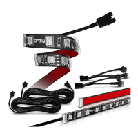
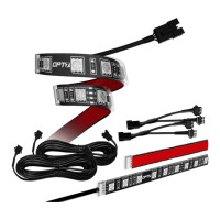
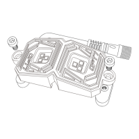
Decide where to locate the control box and ensure wiring has enough length for light bars.
Connect the Red line(+) of power harness to the vehicle battery's positive terminal.
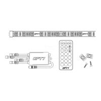
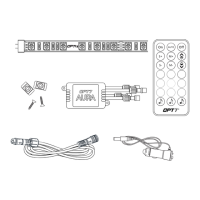
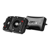
Secure Control box in desired location with Velcro or zipties.
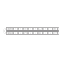
Secure the light bars using the zip ties to tie all the wiring away from the moving components.
Using the included E-Z Remote, select your desired color or pattern.
Connect the control wire (wire with yellow sticker) to an ACC/On power source.
Connect the control wire (red) to the trigger wire and test with car keyfob.
Confirm if the DRL is still on after unlocking the vehicle.
Confirm if the DRL is a halogen lamp.
Open the engine room and find the positive wire of the DRL.
Connect the trigger wire (red) to the DRL positive wire.
| Brand | OPT7 |
|---|---|
| Series | AURA |
| Color Options | Multi-Color |
| Water Resistance | Yes |
| Lighting Type | LED |
| Waterproof Rating | IP67 |
| Control Method | Wireless Remote |
| Lighting Effects | Multiple |
| Installation | Adhesive |
| Power Source | 12V DC |
| Compatibility | Universal |
| Type | LED Underglow Lighting Kit |