Do you have a question about the OptiPure OP175 and is the answer not in the manual?
| Brand | OptiPure |
|---|---|
| Model | OP175 |
| Category | Water Filtration Systems |
| Language | English |
Electrical work must be performed by a qualified electrician per codes.
Information for local maintenance, service, and technical support inquiries.
Specifies operating conditions such as altitude, temperature, humidity, and voltage.
Lists 10 critical safety precautions for connecting and using the system.
Covers Water Quality Indicator, Sample Port, and related valves.
Details the Feed water Inlet and Reject Water Outlet connections.
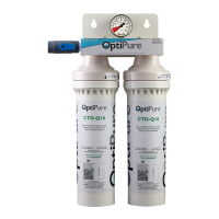
Explains the CTO-Q10 Pre-Filters and MA-Q10 Mineral Addition Cartridge.
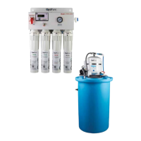
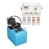
Describes the Buffer Tank, Repressurization Pump, and Storage Tank.
Covers operating parameters, production rates, and recovery.
Details location, feed water, electrical, and drain requirements.
Outlines feed water quality needs and storage tank placement.
Guides on connecting feed water, reject, optimized water, and repressurization lines.
Covers connections and operation of tank inlet and bypass valves.
Details power connection and essential installation precautions.
Step-by-step guide for securely mounting the processor to a wall.
Details connecting drain, feed water lines, and other tubing per instructions.
Detailed front and side view measurements for the processor.
Detailed front and side view measurements for the 16 gal. tank.
Specifies required space for service and cartridge removal.
Steps for preparing QT heads and installing CTO-Q10, AMS-QT15, MA-Q10 cartridges.
Connects reject tubing and prepares for optional sample port use.
Instructions for relocating the Repressurization Pump and Buffer Tank assembly.
Position bypass valve, flush system, and check for leaks.
Fill storage tank using bypass, then start RP pump to purge air.
Connect to distribution, open valves, and read TDS levels.
Incoming water is filtered; bypass valve controls water flow path.
Low tank level activates membrane; full tank closes processor flow.
Explains how to use the monitor to measure feed and permeate TDS.
Pump draws water, refills buffer tank based on pressure switch.
Details optional filters and using bypass for water flow if pump fails.
Methods to measure flow rate or drain the storage tank using sample port.
Identifies feed water, optimized water, and reject water tubing connections.
Labels automatic shutoff valve, pressure gauge, and conductivity probes.
Lists CTO-Q10 PreFilters, AMS-QT15 Membrane, and Mineral Addition Cartridge.
Details the buffer tank, its valve, and bypass check valve.
Identifies the RP Pump, its bracket, and the air breather filter.
Shows the 16 Gal. Storage Tank and the Tank Inlet Divert Valve.
Steps for replacing CTO-Q10 pre-filters and mineral addition cartridge.
Procedure for changing post-treatment cartridges if applicable.
Step-by-step guide for removing and installing the AMS-QT15 membrane.
Lists common problems, possible causes, and resolutions for the system.
Description of fittings and how to prepare tubing for connection.
Detailed instructions on inserting and releasing tubing from fittings.