-52 -
4.1 Process interface
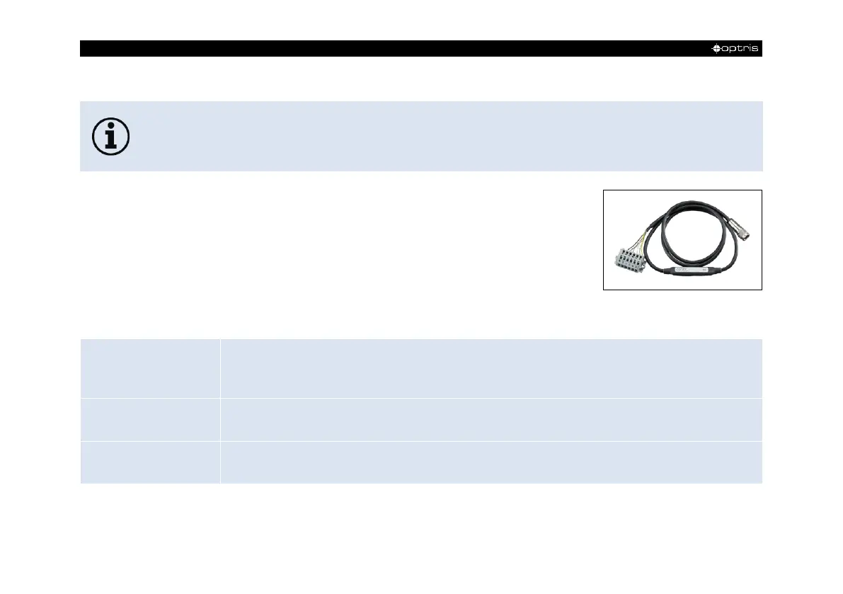
The process interface (electronics within cable as well as industrial interface) must be powered
separately (5-24 VDC). Before switching on the power the PIF cable must be connected to the
camera.
The PI is equipped with a process interface (cable with integrated
electronics and terminal block), which can be programmed via the
software as an Analog Input (AI) and Digital Input (DI) in order to
control the camera or as an Analog Output (AO) in order to control
the process. The signal level is always 0-10 V (DI = 24 V).
The process interface can be activated choosing the following options:
Emissivity, ambient temperature, reference temperature, uncommitted value, flag control, triggered recording,
triggered snapshots, triggered linescanner, triggered event grabber, reset peak-/value-hold, switch temperature
range
Main measure area, measure area, internal temperature, flag status, recording status, line scan status, alarm,
frame sync, fail-safe, external communication
Flag control, triggered snapshots, triggered recording, triggered linescanner, triggered event grabber, reset peak-
/value-hold, switch temperature range
 Loading...