106
UTILISATION
7
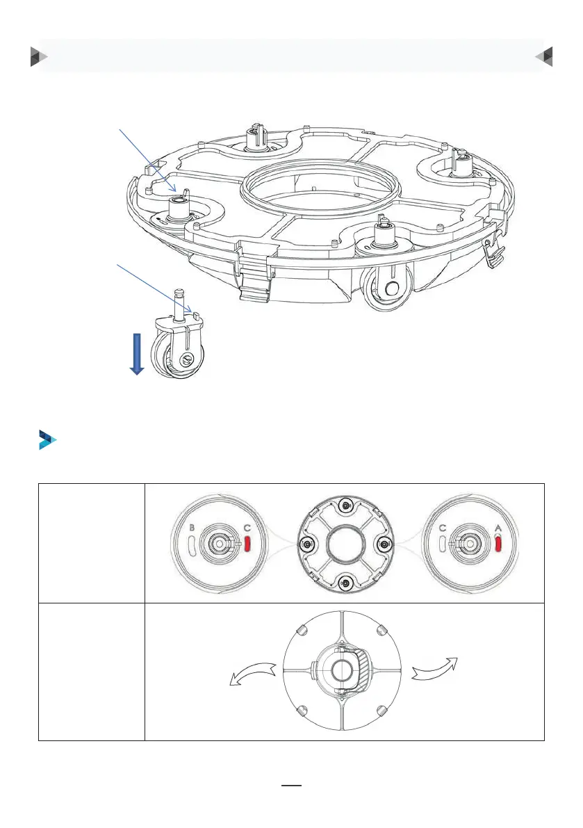
Groove for wheel limit piles
A, B, C are printed on the groove of the wheel limit pile of the chassis. Wheel limit piles will be
installed by default on C (left) and A (right).
Wheel buckle
Wheel limit pile
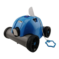
As shown in the figure, push the wheel buckle, pull down the wheel components, and remove them.
Wielhoek
Looppad
ER WORDEN VIER INSTELLINGEN VOOR WIELEN AANBEVOLEN:
Instelling 1: standaardinstelling: C-A, voor de meeste zwembaden
Wielgesp
Wielbegrenzingsnok
Zoals weergegeven in de afbeelding, druk op de
wielgesp, trek de wielcomponenten naar beneden en
verwijder ze.
Herinstalleer vervolgens de wielbegrenzingsnok op het onderstel om de verschillende
looppaden te verwezenlijken.
BEDIENINGSINSTRUCTIES
8
Then re-install the limit pile into chassis to realize the different running paths.
b. Four settings for wheels are recommended:
Setting 1: default setting: B-C, for most of pools
9
Setting 2: C-A, when the turning angle is too large
9
Setting 2: C-A, when the turning angle is too large
9
Setting 2: C-A, when the turning angle is too large