26
7
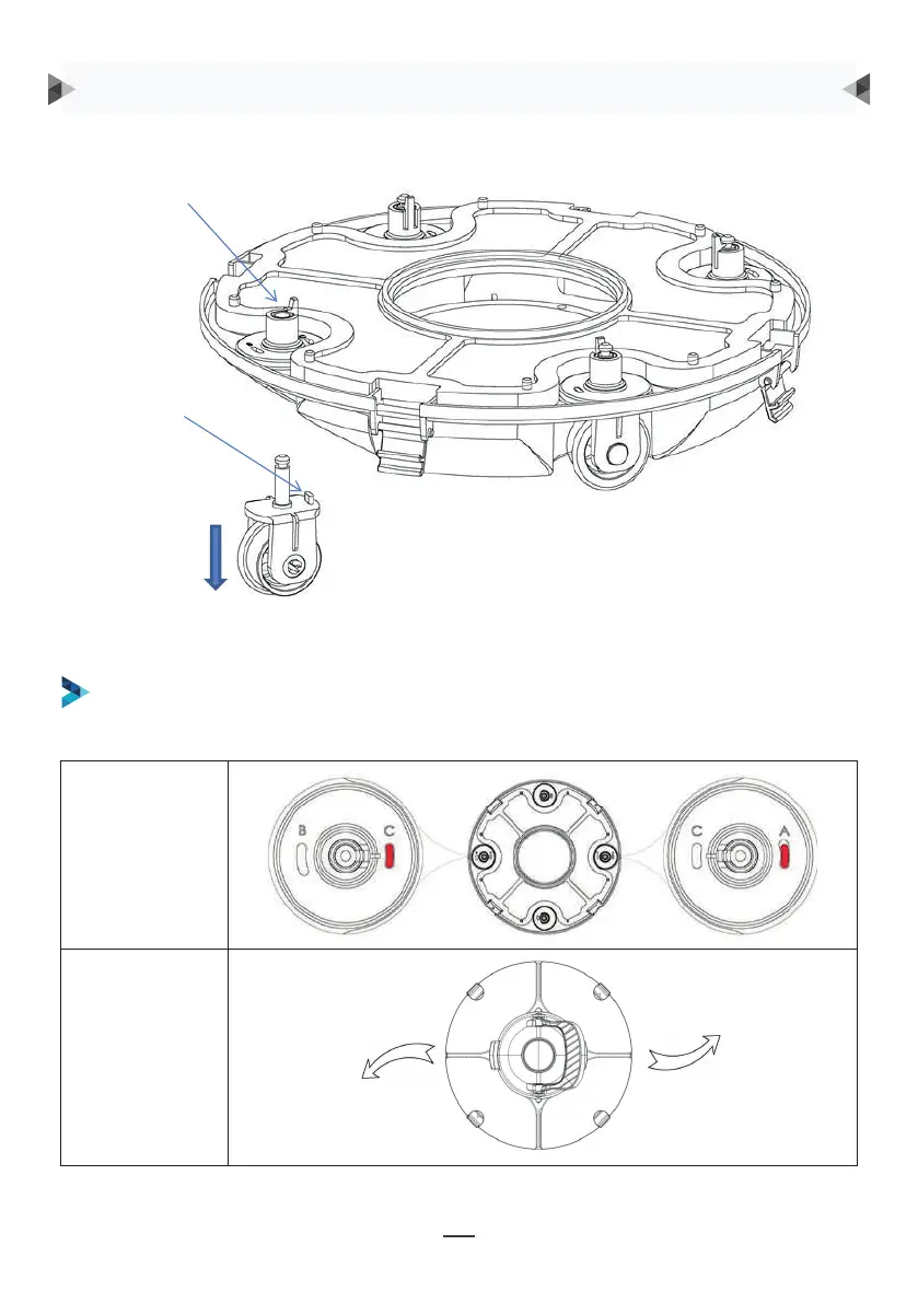
Groove for wheel limit piles
A, B, C are printed on the groove of the wheel limit pile of the chassis. Wheel limit piles will be
installed by default on C (left) and A (right).
Wheel buckle
Wheel limit pile
As shown in the figure, push the wheel buckle, pull down the wheel components, and remove them.
Wheel Angle
Running path
FOUR SETTINGS FOR WHEELS ARE RECOMMENDED:
Setting 1: default setting: C-A, for most of pools
Wheel buckle
Wheel limit pile
As shown in the figure, push the wheel buckle, pull down
the wheel components, and remove them.
Then re-install the limit pile into chassis to realize the dierent running paths.
OPERATING INSTRUCTION
8
Then re-install the limit pile into chassis to realize the different running paths.
b. Four settings for wheels are recommended:
Setting 1: default setting: B-C, for most of pools
9
Setting 2: C-A, when the turning angle is too large
9
Setting 2: C-A, when the turning angle is too large
9
Setting 2: C-A, when the turning angle is too large