42
COMPOSITION DU COFFRET
7
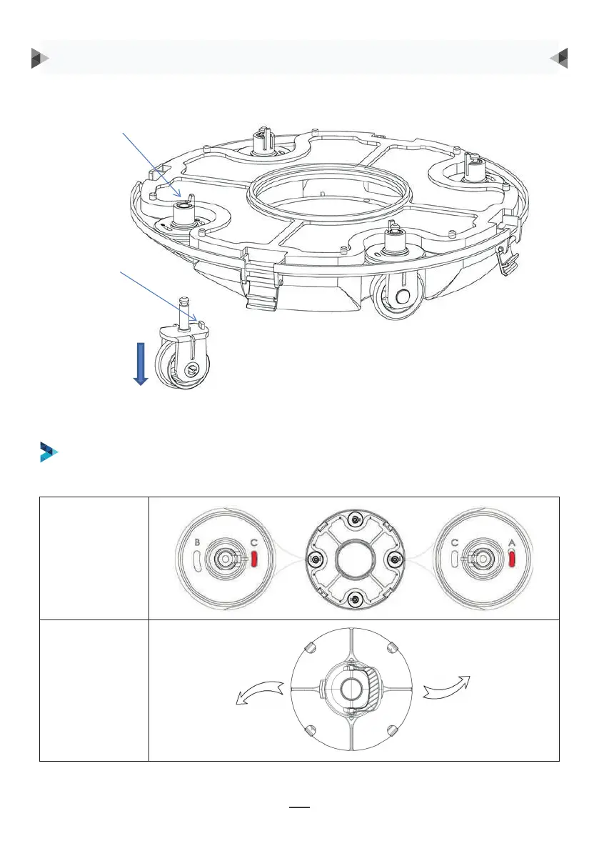
Groove for wheel limit piles
A, B, C are printed on the groove of the wheel limit pile of the chassis. Wheel limit piles will be
installed by default on C (left) and A (right).
Wheel buckle
Wheel limit pile
As shown in the figure, push the wheel buckle, pull down the wheel components, and remove them.
Réglage des
roues
Trajectoire
QUELQUES RÉGLAGES DES ROUES RECOMMANDÉS
Réglage 1 : réglage d’usine par défaut C-A, pour la plupart des piscines :
Clips
ergots de positionnement
Comme indiqué sur le schéma, pousser verticalement
sur les clips pour libérer les roulettes, puis les ré-installer
en positionnant les ergots de positionnements dans
la rainure adéquate selon le réglage souhaité indiqué
ci-après.
FONCTIONNEMENT DU ROBOT
8
Then re-install the limit pile into chassis to realize the different running paths.
b. Four settings for wheels are recommended:
Setting 1: default setting: B-C, for most of pools
9
Setting 2: C-A, when the turning angle is too large
9
Setting 2: C-A, when the turning angle is too large
9
Setting 2: C-A, when the turning angle is too large