21
OWNER SERVICE
Cleaning
After Each Use
• Remove large debris such as clumps of dirt, grass, crop
residue, etc. from machine.
• Inspect machine and replace worn or damaged parts.
• Replace any safety decals that are missing or not readable.
Periodically or Before Extended Storage
• Clean large debris such as clumps of dirt, grass, crop
residue, etc. from machine.
• Remove the remainder using a low-pressure water spray.
1. Be careful when spraying near scratched or torn safety
decals or near edges of decals as water spray can peel
decal off surface.
2. Be careful when spraying near chipped or scratched
paint as water spray can lift paint.
3. If a pressure washer is used, follow the advice of the
pressure washer manufacturer.
• Inspect machine and replace worn or damaged parts.
• Sand down scratches and the edges of areas of missing
paint and coat with Oregon spray paint of matching color
(purchase from your Oregon dealer).
• Replace any safety decals that are missing or not readable
(supplied free through your Oregon dealer).
See Safety Decals section for location drawing.
• Lower skid shoes and park stand to the lowest position for
stability during storage.
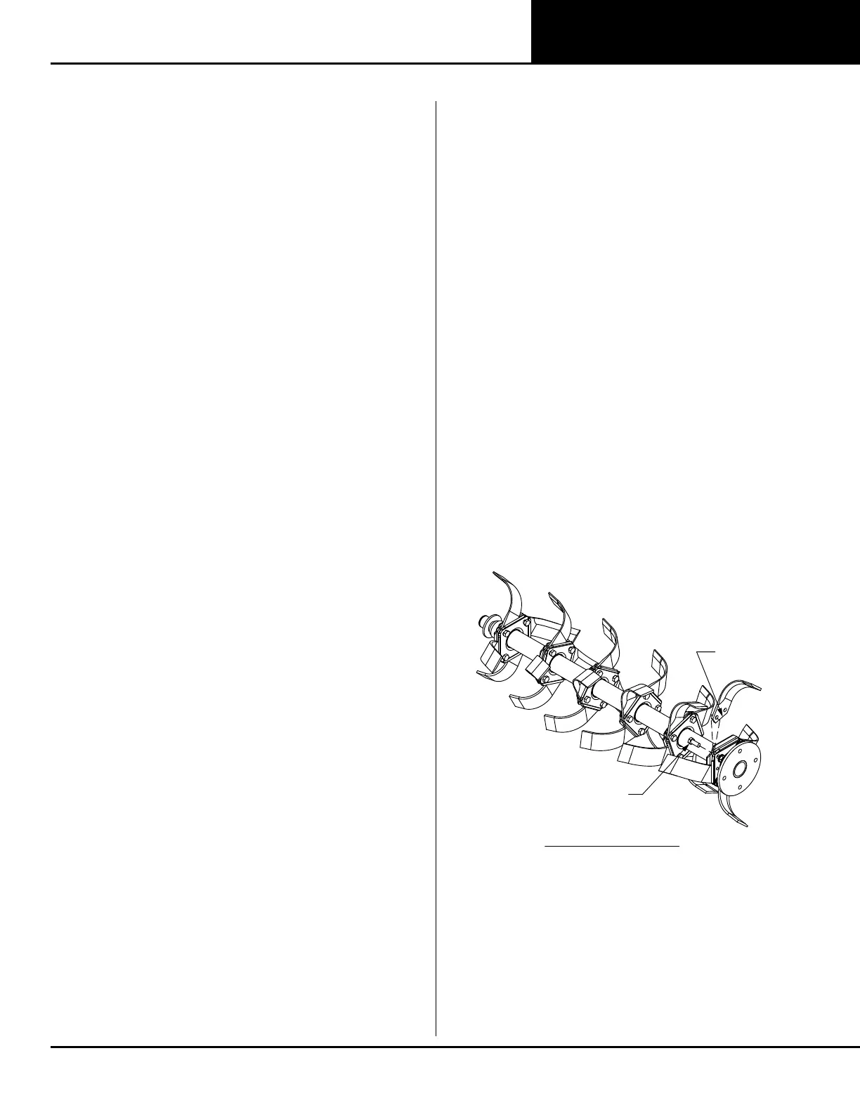
Blade Installation
Four Blade Installation
1. Remove any burrs on flanges generated from blades that
have slipped.
2. Start blade assembly with first blade installed next to rotor
shaft flange.
Blade cutting edges should face the direction
of rotation.
3. Install blade inside flange pocket with blade hole closest to
end matching holes in flanges.
4. Install bolt through flange, blade, flange, and nut but do not
tighten completely.
5. Rotate blade backwards until blade profile is seated on
flange embossments in the flange pockets.
6. Tighten bolted joint to 140 lbs-ft.
7. Proceed by installing next blade of the same part number
in next flange.
8. Repeat steps 2-7 installing opposite hand blade in next
flange hole until all four rows of blades are installed.
Figure 16. Four Blade Forward Rotation Blade Installation
TIGHTEN TO
140 LBS-FT
INSERT BLADE PROFILE
INTO FLANGE POCKET
AGAINST EMBOSSMENT
INSERT BLADE PROFILE
INTO FLANGE POCKET
AGAINST EMBOSSMENT
TIGHTEN
TO 140 LBS-FT
FORWARD ROTATION