26
ASSEMBLY
Assembly
It is important to follow all of the instructions below related
to assembly. Please read the entire section and ensure you
understand all of the required steps. If you need any help,
or if parts are missing, please contact your Oregon dealer
at 1-800-525-8322.
• Do not allow bystanders in the area when operating,
attaching, removing, assembling, or servicing
equipment.
• Do not modify or alter or permit anyone else to modify or
alter the equipment or any of its components in any way.
CAUTION
Always wear relatively tight and belted clothing to
avoid getting caught in moving parts. Wear sturdy,
rough-soled work shoes and protective equipment for
eyes, hair, hands, hearing, and head; and respirator
or filter mask where appropriate.
Set-Up Instructions
The rotary tiller is shipped partially assembled. Assembly
will be easier if components are aligned and loosely
assembled before tightening hardware. See “Bolt Torque
Chart" on page 36 for recommended torque values.
Select a suitable working area. Refer to illustrations,
accompanying text, parts lists, and exploded view drawings.
For reference, front, back, left, and right directions are
determined by sitting in the tractor operator’s seat.
Disassemble Shipping Unit
It is advisable to have a mechanical lifting device to facilitate
uncrating. Be careful of nails in boards when uncrating.
1. Remove all parts that are wired and strapped to tiller and/
or crate.
2. Remove top, sides, and ends of crate.
3. Remove front rubber shield from the bottom of the crate
(reverse rotation models only).
4. Remove lag screws from L-shaped shipping brackets.
Remove L-brackets from the tiller.
5. Remove tiller assembly from crate base.
6. Remove loose nails from boards and dispose of crate
according to local codes.
Assembly Procedures
Required tools: 1/2", 9/16", 3/4", 1-1/8", and 13 mm
combination wrenches, sockets, torque wrench, and
jack stands.
1. Lower skid shoes to lowest position and stand tiller
upright.
2. Lower park stand to support the front of the tiller with tiller
sitting on the ground.
3. Install driveline shield (18) to gearbox input shaft using 8
mm bolts (38), 5/16 flat washers (39) and lock washers
(40).
4. Install driveline (19) to gearbox input shaft. (Refer to page
12 for driveline attachment to tractor).
5. Attach mast plates (6 & 7) to tiller frame using 1/2" x
1-1/4" and 1/2" x 1-1/2" cap screws (45 & 46), and flange
lock nuts (48). Attach gearbox mount (22) to gearbox with
1/2" x 1" cap screws (47). Secure to mast plates with 1/2" x
1" cap screws and 1/2" flange lock nuts.
6. Assemble Cat 1 quick hitch sleeve (56) between mast
plates in lower hole in the top of mast plates. Secure with
3/4" x 3-1/2" cap screw (55) and lock nut (57).
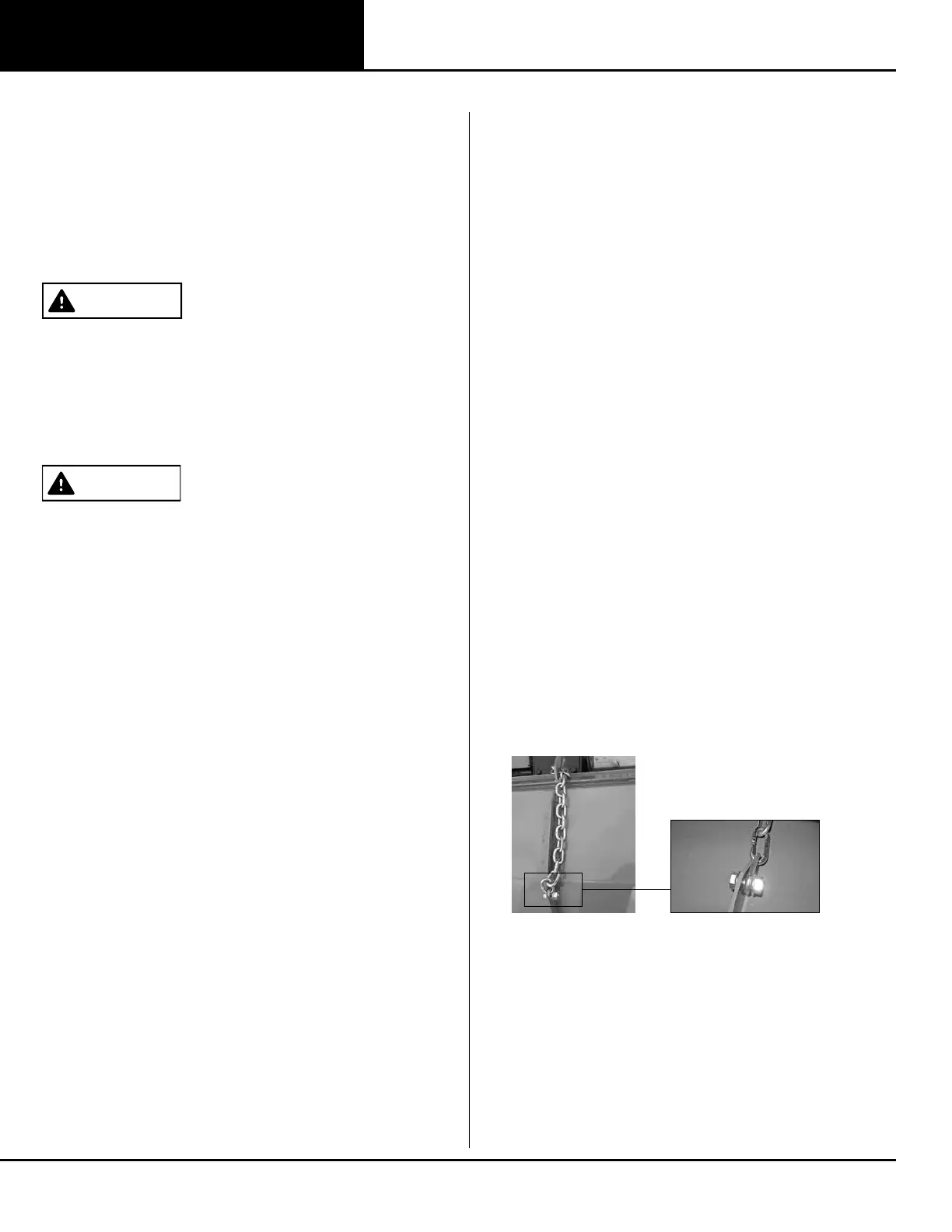
7. Attach tailgate chain to tailgate using 1/2" x 1" cap screw
(47) and flange lock nut (48). Thread the chain through the
keyhole slot on the top of tiller frame. Secure the chain by
sliding the desired link into the narrow portion of the
keyhole slot.
Figure 24. Attaching Tailgate Chain
8. Fill both gearboxes with SAE 80W or 90W gear lube until it
runs out the side level plug.
9. Use a 5/16" Allen wrench to remove the fill plug.