8
Unauthorized reproduction or copying of all or part of this manual is
prohibited.
Oriental Motor shall not be liable whatsoever for any problems relating
to industrial property rights arising from use of any information, circuit,
equipment or device provided or referenced in this manual.
Characteristics, specications and dimensions are subject to change
without notice.
While we make every eort to oer accurate information in the manual,
we welcome your input. Should you nd unclear descriptions, errors or
omissions, please contact the nearest oce.
is a registered trademark or trademark of Oriental Motor
Co., Ltd., in Japan and other countries.
Modbus is a registered trademark of the Schneider Automation Inc.
CC-Link is a registered trademark of the CC-Link Partner Association.
MECHATROLINK is a registered trademark of the MECHATROLINK
Members Association.
EtherCAT® is registered trademark and patented technology, licensed by
Beckho Automation GmbH, Germany.
© Copyright
ORIENTAL MOTOR CO., LTD. 2011
Published in June 2019
echnical Support Tel:(800)468-3982
A.M. to 5:00 P.M., P.S.T. (M-F)
A.M. to 5:00 P.M., C.S.T. (M-F)
.orientalmotor.com
Schiessstraße 44, 40549 Düsseldor
f, Germany
echnical Support Tel:00 800/22 55 66 22
.orientalmotor.de
el:01256-347090
.oriental-motor.co.uk
el:01 47 86 97 50
.orientalmotor.fr
el:02-93906346
.orientalmotor.it
el:+55-11-3266-6018
.orientalmotor.com.br
• Please contact your nearest Oriental Motor oce for further information.
4-8-1Higashiueno
,Taito-ku,Tokyo 110-8536
el:03-6744-0361
.orientalmotor.co.jp
Tel:0800-060708
www.orientalmotor.com.tw
Singapore
Tel:1800-8420280
www.orientalmotor.com.sg
Tel:1800-806161
www.orientalmotor.com.my
Korea
Tel:080-777-2042
www.inaom.co.kr
Tel:1800-888-881
www.orientalmotor.co.th
Tel:400-820-6516
www.orientalmotor.com.cn
Tel:+91-80-41125586
www.orientalmotor.co.in
Hong Kong Branch
z
I/O connector function table
This gure is the CN4 connector
viewed from the driver front side.
Pin
No.
Signal
type
Terminal
name
Signal name Description
1
Input
X0 FWD
The motor turns in the
clockwise direction.
2 X1 REV
The motor turns in the
counterclockwise direction.
3 X2 STOP-MODE
Select instantaneous stop
or deceleration stop.
4 X3 M0
Select the internal
potentiometer or external
potentiometer (external DC
voltage).
5 GND C0 IN-COM −
6
Output
Y2 SPEED-OUT
30 pulses are output with
each revolution of the
motor output shaft.
7 Y1− WNG (−) −
8 Y0−
ALARM-OUT1
(−)
−
9
Input
X4 ALARM-RESET Alarms are reset.
10 X5 MB-FREE
Select how the
electromagnetic brake
would operate when the
motor stops.
11
Analog
input
VL VL
External speed setting
input; Set the speed of
the external potentiometer
(external DC voltage).
12 VM VM
13 VH VH
14
Output
Y1+ WNG (+)
This signal is output when
a warning generates.
15 Y0+
ALARM-OUT1
(+)
This signal is output
when an alarm generates
(normally closed).
Electromagnetic brake type only.
Overview of the operation
Basic operation
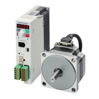
With the
BLV
Series, you can perform following operations. Refer to USER
MANUAL Basic Function for details.
Speed setting
Internal potentiometer, external potentiometer, external DC voltage
Running/stopping the motor
Run/stop the motor by inputting operation control signals.
Setting the acceleration time and deceleration time
You can set the acceleration time and deceleration time for starting and
stopping.
2-speed operation
Operation can be performed at two speeds through use of both the internal
potentiometer and external potentiometer (external DC voltage).
Multi-motor control
A single external potentiometer (external DC voltage) can be used to set the
same speed for multiple motors.
If the support software
MEXE02
or the data setter
OPX-2A
(sold separately)
is used, the function can be extended so that the digital setting of the rotation
speed and torque limiting value, the setting of parameters, and various
monitors can be performed.
Operation via communication
z
RS-485 communication
Operation data and parameters can be set and operation commands can be
input from the host controller via RS-485 communication. The protocol
for the RS-485 communication is the Modbus protocol. Refer to the USER
MANUAL RS-485 Communication Mode for details.
z
Network converter
This product can be used via various network when connecting to a network
converter (sold separately). Refer to the operating manual of the network
converter for details.
Network converter model Supported network
NETC01-CC
CC-Link
NETC01-M2
/
M3
MECHATROLINK
NETC01-ECT
EtherCAT
Refer to the USER MANUAL for details on the product.
For the USER MANUAL, contact your nearest Oriental
Motor sales oce or download from Oriental Motor Website
Download Page.

 Loading...


