EasyManua.ls Logo

Oriental motor BLVD20KM User Manual

Oriental motor BLVD20KM
72 pages
To Next Page IconTo Next Page
Page #1 background imageLoading...
Page #1 background image
HM-5113-9
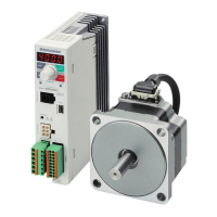
Brushless Motor and Driver Package
BLV
Series
Standard Type, Electromagnetic Brake Type
USER MANUAL (Basic Function)
Thank you for purchasing an Oriental Motor product.
This Manual describes product handling procedures and safety precautions.
Please read it thoroughly to ensure safe operation.
Always keep the manual where it is readily available.

Table of Contents

Other manuals for Oriental motor BLVD20KM

Questions and Answers:

Oriental motor BLVD20KM Specifications

General IconGeneral
BrandOriental motor
ModelBLVD20KM
CategoryEngine
LanguageEnglish

Summary

2 Safety precautions

6 Installation

Installation location

Specifies conditions for installing the motor and driver in a suitable location.

6.3 Installing a load

Explains how to install loads on parallel shaft and round shaft types.

Combination type-hollow shaft flat gearhead

Advises using stepped load shafts and applying grease for hollow shaft gearheads.

6.4 Permissible radial load and permissible axial load

Provides permissible load values for parallel shaft gearhead types.

6.5 Installing the driver

Details how to install the driver using screws in vertical or horizontal orientation.

6.7 Installing and wiring in compliance with EMC Directive

Provides guidelines for wiring power and signal cables for EMC compliance.

7 Connection

7.1 Connecting the power supply

Explains the step-by-step method for connecting the power supply.

7.2 Connecting the motor and driver

Specifies maximum extension distances for motor and driver connection cables.

7.3 Connecting the I/O signals

Details the input signal circuit configuration for the driver.

Input signals

Explains the behavior and function of various input signals (FWD, REV, STOP-MODE, etc.).

FWD input and REV input

Explains the function of Forward and Reverse input signals for motor control.

Output signals

Describes the driver's output signals, including SPEED-OUT and ALARM-OUT1.

7.4 Connecting the communication cable

Connects a MEXE02 or OPX-2A to the communication connector (CN7).

7.5 Connection diagram (example)

Shows an example connection diagram for sink logic inputs and outputs.

8 Operation

Basic operation

Covers fundamental operations like speed setting and motor start/stop.

Speed setting

Explains how to set motor speed using internal/external potentiometers or DC voltage.

Setting by internal potentiometer

Details how to adjust speed using the internal potentiometer (VR1).

Setting by external potentiometer (sold separately)

Explains connecting and using an external potentiometer for speed setting.

Setting by external DC voltage

Describes setting motor speed using external DC voltage inputs.

Operation and stop of motor

Explains how to start and stop the motor using input signals.

Stop

Details the methods for stopping the motor based on input signal states.

8.3 Setting the acceleration time and deceleration time

Sets the acceleration and deceleration times for motor starting and stopping.

8.4 Speed response selection

Allows selection between high response and regenerative power suppression modes.

8.5 Two-speed operation

Explains how to operate the motor at two different speeds using M0 input.

8.7 Torque limiting function

Explains how to set and use the motor's torque limiting function.

8.8 Sink logic/Source logic selection

Illustrates I/O signal connection examples for sink and source logic.

8.9 Multi-motor control

Explains how to connect multiple drivers for multi-motor control using a potentiometer.

10 How to use MEXE02

Starting MEXE02

Guides on how to start and configure the MEXE02 software.

Setting the operation data

Explains how to set operation data, including data entry and selection.

Data entry

Details how to enter numeric values and select options in MEXE02.

Setting of parameters

Guides on how to edit and write parameters to the driver using MEXE02.

10.4 Monitor

Explains how to use the unit information monitor to check driver settings and status.

Unit information monitor

Explains how to use the unit information monitor to check driver settings and status.

Status monitor

Details how to use the status monitor to check motor feedback speed and load factor.

Alarm monitor

Guides on checking alarm history, resetting alarms, and clearing history.

Warning monitor

Explains how to check warning conditions and history.

Waveform monitor

Explains how to check motor speed and I/O signals in a waveform format.

10.5 Test operation

Explains how to operate the motor and check data via MEXE02.

Teaching/remote operation

Explains how to operate the motor and check data via MEXE02.

I/O test

Details how to test I/O signals and check connections with a controller.

11 Setting contents of MEXE02

11.2 Parameter list

Lists parameters related to operation data, including setting ranges and factory settings.

11.3 Function setting

Explains setting the speed reduction ratio for monitoring gearhead output shaft speed.

11.4 I/O function selection

Assigns functions to input terminals X0 through X5.

11.5 Alarm and warning

Controls whether undervoltage alarms are latched or automatically cleared.

11.6 Test operation and display

Sets the rotation speed for JOG operation using the data setter.

11.7 Operation setting

Selects the initial screen displayed when the driver power is turned on.

11.8 Communication

Sets the condition for communication timeout in RS-485.

13 Protective functions

Alarm lists

Lists alarm types, causes, remedial actions, and reset methods based on LED blinks.

14 Troubleshooting and remedial actions

The motor does not rotate.

Lists possible causes and solutions when the motor fails to rotate.

The motor rotates in the opposite direction against the specified direction.

Addresses issues with incorrect motor rotation direction.

Motor operation is unstable.

Provides troubleshooting steps for unstable motor operation or vibration.

The motor does not stop instantaneously.

Troubleshoots issues where the motor fails to stop instantaneously.

The electromagnetic brake does not hold the load in position.

Provides solutions for electromagnetic brake holding issues.

15 Specifications

15.4 Pin assignment

Shows pin assignments for the connection cable (Connectors 1, 7, 4, 2, 8, 5).

Related product manuals