Do you have a question about the Oriental motor BXII Series and is the answer not in the manual?
This document describes the Oriental Motor BX II Series Brushless Motor and Driver Package, an integrated solution designed for industrial equipment applications. It covers the product's functions, usage, and maintenance procedures, emphasizing safety precautions throughout.
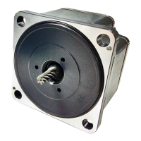
The BX II Series offers a comprehensive motor and driver package for precise control in various industrial settings. The system is capable of both speed control and position control modes, which can be configured via switches on the driver.
The driver features an operation panel with a display and keys for monitoring, setting parameters, and executing test operations. It includes internal potentiometers for adjusting motor operation speed, acceleration time, and deceleration time. External control is also supported through input signals, allowing for functions such as forward (FWD), reverse (RVS), and instantaneous stop (STOP). Output signals provide feedback on motor status, including alarms and movement.
For applications involving vertical drive, gravitational operation, or large inertial loads, an accessory regeneration unit (EPRC-400P or RGB100) can be connected to manage regenerated energy, protecting the driver from damage. The system also supports external potentiometers (PAVR-20KZ) or external DC voltage for setting operation speed or torque limiting.
The motor and driver are designed as Class I equipment, requiring proper grounding of their Protective Earth Terminals for safety. The driver incorporates protective functions against overheating, poor connections, and operational errors, issuing alarms and warnings to ensure safe operation. These protective functions include detection of excessive position deviation, overcurrent, overvoltage, undervoltage, sensor errors, and main circuit output errors.
The BX II Series is intended for installation in general industrial equipment within a well-ventilated enclosure, free from explosive or corrosive environments, flammable gases, splashing water, excessive dust, and strong electromagnetic noise. The system requires a stable power supply within specified voltage ranges, and it is crucial to use the supplied conversion cables for connecting the motor and driver to prevent malfunctions.
Installation of the motor and gearhead involves securing them to mounting plates using hexagonal socket head screws, ensuring no gaps remain. For hollow shaft flat gearheads, a safety cover is provided for the end opposite the load shaft. When installing a load, proper alignment of the motor/gearhead output shaft with the load shaft is essential, along with secure fastening using couplings, belts, or gears, avoiding excessive force that could damage bearings or shafts. The output shafts are designed with key slots for parallel shaft gearheads and flat sections for round shaft types to facilitate load attachment.
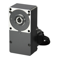
The driver can be installed using screws, mounted to a DIN rail with an accessory plate (MADP02), or secured with a mounting bracket. Clearances must be maintained around the driver for proper heat dissipation. For input signals, the system allows selection between a built-in power supply or an external power supply, with specific lead wire and crimp terminal requirements.
Test operation, or JOG operation, can be performed to check the motor and driver connection and basic functionality. This mode allows the motor to rotate in forward or reverse directions at a predefined speed, acceleration, and torque, which can be adjusted via parameters. It is crucial to ensure that motor rotation will not cause any dangerous situations during JOG operation and that input signals like FREE or STOP are turned OFF.
The system includes an edit lock function to prevent accidental changes to parameters, which can be enabled or disabled via the operation panel.
Regular maintenance and inspection are critical for the safe and prolonged operation of the BX II Series. Before any maintenance or inspection, the power supply must be turned off, and sufficient time allowed for residual voltage to dissipate (until the CHARGE LED turns off) to prevent electric shock.
Periodic inspections should include checking for loose mounting screws on the motor/gearhead, unusual noises from motor or gearhead bearings, misalignment of the output shaft with the load shaft, scratches or damage to cables, blocked openings in the driver, loose connection terminals, and any unusual smells or appearances from the driver.
Insulation resistance and dielectric strength tests should be conducted separately on the motor and driver to avoid damage. The driver's semiconductor elements require careful handling to prevent damage from static electricity. It is also important not to conduct these tests on the encoder.
In the event of an alarm, the cause must be identified and resolved before resetting the protective function. Continuing operation without addressing the underlying problem can lead to further malfunction, injury, or equipment damage. For issues such as excessive position deviation, overcurrent, overvoltage, or overload, remedial actions include decreasing the load, reviewing operating conditions (acceleration/deceleration time), checking wiring, and ensuring proper power supply voltage. If an alarm persists, contacting the nearest Oriental Motor sales office is recommended.
The non-volatile memory for saving data has a rewrite limit of approximately 100,000 times, and power should not be turned off during or immediately after data writing to prevent EEPROM errors. The product should be disposed of correctly in accordance with local laws and regulations. Disassembly or modification of the motor or driver is prohibited and should be referred to authorized service centers.
| Insulation Class | Class B |
|---|---|
| Frame Size | 60 mm, 80 mm |
| Power Supply | Single-phase 100V, 200V |
| Control Method | Speed control |
| Gear Ratio | 3:1 to 180:1 |
| Enclosure | Totally Enclosed |
| Voltage | 100 VAC, 200 VAC |