H07401<2>
6
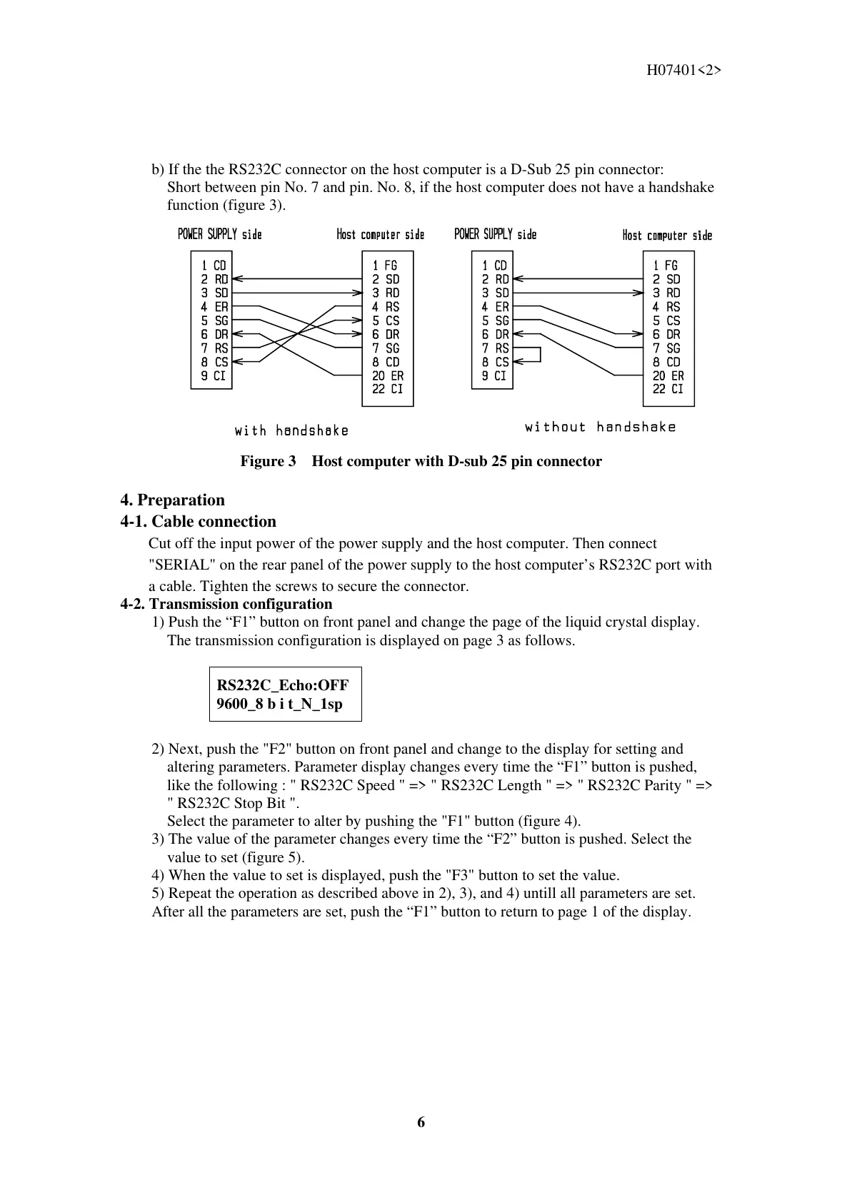
b) If the the RS232C connector on the host computer is a D-Sub 25 pin connector:
Short between pin No. 7 and pin. No. 8, if the host computer does not have a handshake
function (figure 3).
Figure 3 Host computer with D-sub 25 pin connector
4. Preparation
4-1. Cable connection
Cut off the input power of the power supply and the host computer. Then connect
"SERIAL" on the rear panel of the power supply to the host computer’s RS232C port with
a cable. Tighten the screws to secure the connector.
4-2. Transmission configuration
1) Push the “F1” button on front panel and change the page of the liquid crystal display.
The transmission configuration is displayed on page 3 as follows.
RS232C_Echo:OFF
9600_8 b i t_N_1sp
2) Next, push the "F2" button on front panel and change to the display for setting and
altering parameters. Parameter display changes every time the “F1” button is pushed,
like the following : " RS232C Speed " => " RS232C Length " => " RS232C Parity " =>
" RS232C Stop Bit ".
Select the parameter to alter by pushing the "F1" button (figure 4).
3) The value of the parameter changes every time the “F2” button is pushed. Select the
value to set (figure 5).
4) When the value to set is displayed, push the "F3" button to set the value.
5) Repeat the operation as described above in 2), 3), and 4) untill all parameters are set.
After all the parameters are set, push the “F1” button to return to page 1 of the display.
 Loading...