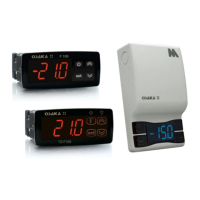
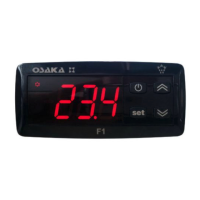
OSAKA - F 100 / TSF 100 / M1 - Manual de Usuario – V2.1 - PAG. 5
Any alarm condition is indicated by the LED ALARM while the
condition is pre alarm or alarm delay is indicated by the flashing
LED. The buzzer can be configured to signal alarms the par. "O.bu"
= 1 or 3 and can be deactivated in case you are playing with the
press of a key.
4.6.1 – TEMPERATURE ALARMS
The alarm function is a function of temperature reading from the
probe, and the type of programmed alarm parameter. "A.Ay" and
the alarm set point par. "A.HA" (maximum alarm) and "A.LA"
(minimum alarm) and the relative differential "A.Ad".
Through the "A.Ay" parameter you can specify whether the alarm
set "A.HA" and ".LA" should be considered absolute ("A.Ay" = 1) or
relative to the Set Point ("A.Ay" = 2).
By some parameters may delay activation, if the situation is
cancelled recovering optimal conditions, without becoming alarm.
These parameters are:
"A.PA" - delay in receiving the alarm and turn on the power control
equipment, should be in alarm.
"A.Da" - delay after defrost (A. maximum) or after a continuous
cycle (A. Min).
"A.At" - delay of the performance of temperature alarm.
The differential alarm will be the same set in parameters "A.HA"
and "A.LA" if alarms are absolute ("A.Ay" = 1).
Or shall result from: ["SP" + "A.HA"] and ["SP" + "A.LA"] if the
alarm is on ("A.Ay" = 2).
The maximum and minimum alarm temperature can be disabled
setting: "A.HA" e "A.LA" = oF.
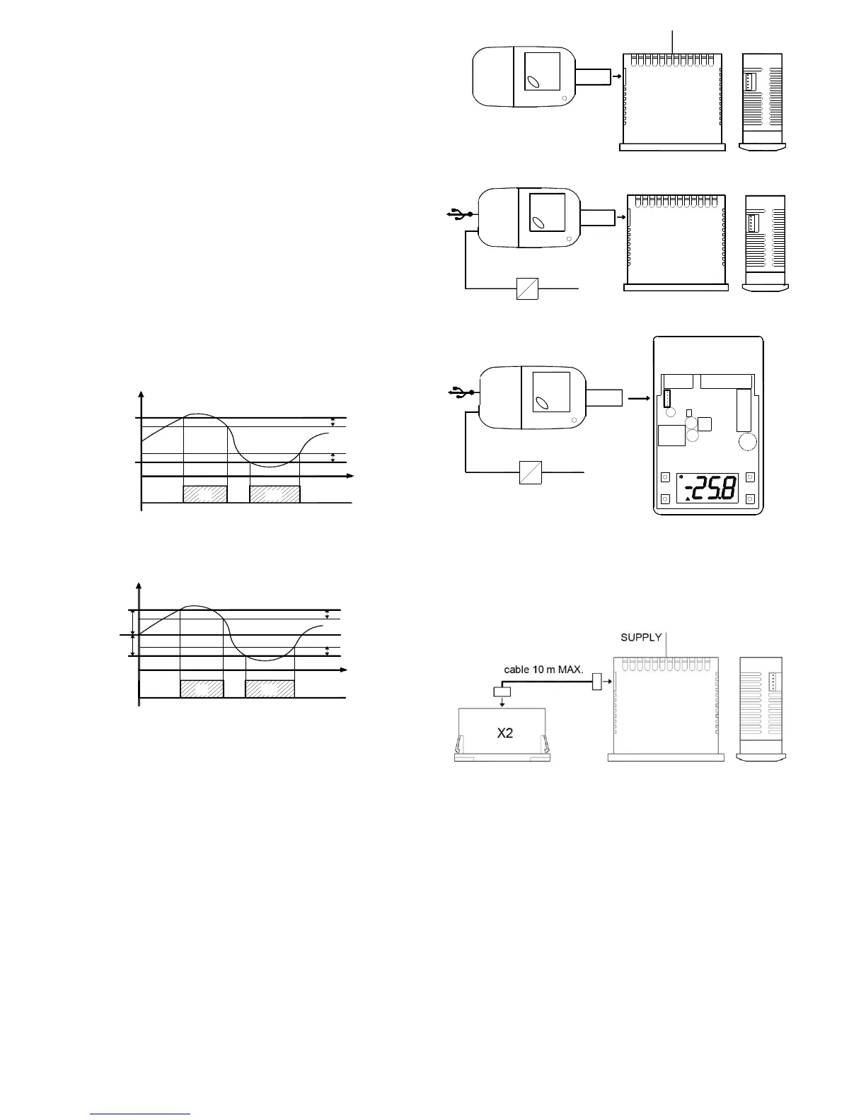
4.7 – ACCESSORIES
4.7.1– KEY USB + OSAKA SETUP: KEY PROGRAMMING
Extracting the box you have access to a white connector that allows
easy programming with programming key 5 pin. This key allows
repetitive schedules and save the settings in a practical and simple.
There are 2 types of Key, the key enabling USB connection pc and
save the different configurations and set parameters and Manual
Key 5 pin only for connecting thermostats.
An advantage and recommendation is the use of the supplied
power supply KEY without connecting the F 100 / TSF 100 / M1 to
power.
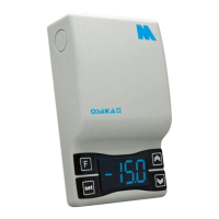
4.7.2 – X2 - REMOTE DISPLAY
The equipment you can connect a remote display device X2 by a
cable that can be up to 10 meters at maximum. The X2 device
powered directly from the device, displays temperature measured
by the probe Pr1 by a 2-digit display and a half.
 Loading...