OSAKA – F 1 – User’s Manual – v1 – PAG. 1
USER’S MANUAL FOR COOL/HEAT
DIGITAL THERMOSTAT WITH
DEFROSTING
User’s Manual – v1
www.osakasolutions.com
in this manual there is the necessary
information for the proper installation and
usage instruction and maintenance of the
product, it is recommended to read it carefully
and to keep it.
In order to avoid dangerous or hazardous
circumstances for people, things or animals due to an
irregular operation or the malfunctioning of the thermostat, we
remind you that the installation must comply with and be
aware of the annexed safety systems, necessary to guarantee
the aforementioned safety.
Neither OSAKA SOLUTIONS nor its legal representatives are
responsible neither for the inadequate use of the
THERMOSTAT nor for the use of it not conforming to the
characteristics of the THERMOSTAT.
INDEX
DESCRIPTION OF THE CONTROLLER
QUICK SELECTION OF THE SET POINT
STANDARD PROGRAMMING OF THE PARAMETERS
PARAMETERS PROTECTION THROUGH PASSWORD
CUSTOMIZING PARAMETERS WITH / WITHOUT
PASSWORD
RESTORATION OF INITIAL PARAMETERS
KEYBOARD LOCKING FUNCTION
USAGE AND INSTALLATION WARNINGS
ELECTRICAL WIRING DIAGRAM
ON / OFF (STAND-BY) FUNCTION
“NORMAL” AND “ECONOMIC” MODE OF OPERATION
INPUTS AND DISPLAY CONFIGURATION
DIGITAL INPUT CONFIGURATION
TEMPERATURE REGULATION
COMPRESSOR PROTECTION AND STARTING DELAY
AUTOMATIC DEFROSTING CONTROL
DEFROSTING BY TIME INTERVALS
DEFROSTING BY THE TEMPERATURE OF THE
EVAPORATOR
DEFROSTING BY CONTINUAL TIME
OF THE COMPRESSOR’S OPERATION
MANUAL DEFROSTING
INTERVALS AND DURATION OF THE DEFROSTING
WITH EVAPORATOR PROBE ERROR
LOCKING OF THE DISPLAY DURING THE
DEFROSTING
4.8.1
4.8.2
4.8.3
4.9
4.10
5
TEMPERATURE ALARMS
EXTERNAL ALARM OF DIGITAL INPUT
OPEN DOOR ALARM
OPERATING KEY “ ” AND “DOWN / AUX”
PARAMETERS CONFIGURATION WITH KEY USB
PARAMETERS LISTING
PROBLEMS, MAINTENANCE AND WARRANTY
MECHANICAL FEATURES
MECHANICAL DIMENSIONS, HOLES AND MOUNTING
FUNCTIONAL FEATURES
1 – DESCRIPTION OF THE CONTROLLER
1.1 – GENERAL DESCRIPTION
The F1 is an electronic digital thermostat with a microprocessor
adequate for applications of refrigeration and industrial processes,
equipped with temperature control with ON / OFF regulation and
defrosting control by compressor shutdown by time intervals.
The controller has one relay output and two NTC (10k) temperature
probe inputs, of which the second input can be used as a digital
input instead of as a probe input.
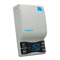
1.2 – FRONTAL PANEL DESCRIPTION
Panel frontal F 1
1 - “SET” KEY: By pressing and releasing quickly you can change
the Set Point.
By pressing for 5 seconds you can access the parameters
programming function. This function is used to edit the parameters
and to confirm the desired value.
It can be used alongside the “UP” key to modify the programming
level of the parameters.
Having the keyboard locked, if you press “SET” + “UP” during 5
seconds the keyboard will be unlocked automatically.
2 – “DOWN” Key:
You can lower the value of the SET POINT by pressing it directly
without having entered the menu. In the parameters menu you can
search the desired parameter and after pressing the selection of
the parameter with “SET” you lower or select the new value of the
parameter.