The temperature alarms of maximum and minimum can be
deactivated if we insert the parameters “A.HA” and “A.LA” = oF.
4.8.2 – EXTERNAL ALARM OF DIGITAL INPUT
The controller can signal an external alarm through the activation of
the digital input with the function programmed as “i.Fi” = 4 or 5.
The controller signals the alarm through the activation of the
ALARM led and the visualization of the label AL alternating it with
the establish variable in the “i.dS” parameter. The mode “i.Fi” = 4
doesn’t operate with any action over the control output whereas the
mode “i.Fi” = 5 foresees the deactivation of the control output in the
intervention of the digital input.
4.8.3 – OPEN DOOR ALARM
The controller can signal an open door alarm through the activation
of the digital input with the function programmed as “i.Fi”= 1, 2 or 3.
When the digital input is deactivated, the controller signals that the
door is open in the display with the oP label alternating it with the
established variable in the “i.dS” parameter. After the delay
programmed in the “A.oA” parameter, the controller signals the
alarm through the activation of the ALARM led and with the display
of the oP label.
In the open door alarm’s intervention the disabled output will be
reactivated.
4.9 – OPERATING KEY “ ” AND “DOWN/AUX”
In addition to its normal functions, two of the controller’s keys can
be configured to do other functions. The key can be defined
with the “t.UF” parameter whereas the function of the “DOWN/AUX”
key is defined with the “t.Fb” parameter.
Both parameters have the possibility of being configured to do one
of the following functions:
= oF – The key doesn’t have any specific function.
= 1 – DO NOT USE
= 2 – By pressing the key for a few seconds, it is possible to select
the rotation of the Normal or Economic (SP/SPE) active operation
modality. When the key is pressed, the display will show (flashing)
for one second the code of the active set point (“SP” or “SPE”).
= 3 – By pressing the key for some seconds it’s possible to change
the controller from an ON state to Stand-by and vice-versa
= 4 – DO NOT USE
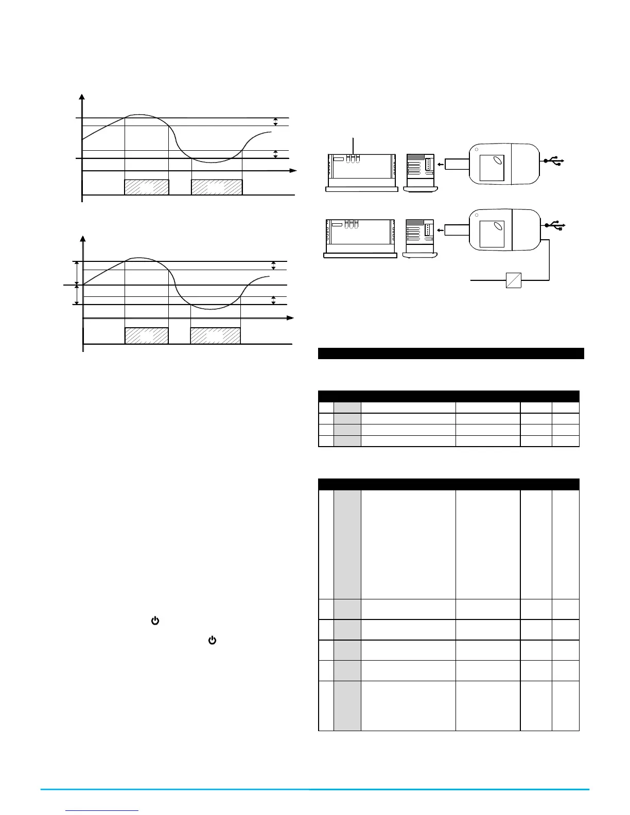
4.10 – PARAMETERS CONFIGURATION WITH KEY USB
The controller has a connector that allows you to transfer the
operation parameters to the KEY USB device, which is equipped
with a connector of 5 poles. The KEY USB device is used to
program the controllers that must have the same configuration of
parameters, or to save a copy of the controller’s programming and
be able to transfer it quickly. The KEY USB has a USB connection
input, which allows connecting it to a PC, with which through the
Universal Conf or Osaka Set Up configuration software it is
possible to configure the operation parameters.
 Loading...