OSAKA – F 1 – User’s Manual – v1 – PAG. 10
6.2 – CLEANING
It is recommended to clean the controller with a wet cloth alone. Do
not use soap nor any other neutral detergent.
6.3 – WARRANTY AND REPAIRING
The controller has a warranty that takes form either in reparation or
in replacement, if the error is due to a manufacturing defect in
materials which are up to 12 months old from the purchasing date.
OSAKA SOLUTIONS will automatically make void this warranty and
will not be held accountable for possible damage that may result
from:
- The use, installation or handling which is inappropriate or
different than the one written here, and specially when is
differs from the safety requirements established by the
regulation.
- The usage in applications, machines or electrical panels
that do not provide adequate protection against liquids,
dust, grease and electric shocks in the conditions of
mounting.
- The inexperienced handling, and / or alteration of the
product.
- The installation / use in applications, machines or
electrical panels that do not comply with the valid norm.
If the product has a defect during the warranty time or outside of
aforementioned time, you should contact the after-sales service to
go through the appropriate procedure. Request a repairing
document “RMA” (by email or fax) and fill it. It is necessary to send
the RMA and the controller to the SAT OSAKA with prepaid
shipping.
7.1 – ELECTRICAL FEATURES
Supply: 115 or 230 VAC +/- 10%
AC Frequency: 50/60 Hz
Consumption: 2 VA
Input: 2 inputs for NTC (103AT-2, 10 K Ω @ 25 °C) temperature
probes; 1 digital input by free voltage contact as an alternative
option to the 2 probe inputs.
Output - 16A -
1HP 250V,
1/2HP 125 VAC
Electrical life relay output: 100000 op. in compliance with EN 60730
Supply: Type 1.B in compliance EN 60730-1
Overvoltage category: II
Device’s class: Class II
Isolation: Isolated by piece low voltage (power 115/230 V and relay
outputs); and part low voltage inputs; electrically isolated between
output and supply.
7.2 – MECHANICAL FEATURES
Body: Self-extinguishing UL 94 V0 plastic.
Category of resistance to heat and fire: D
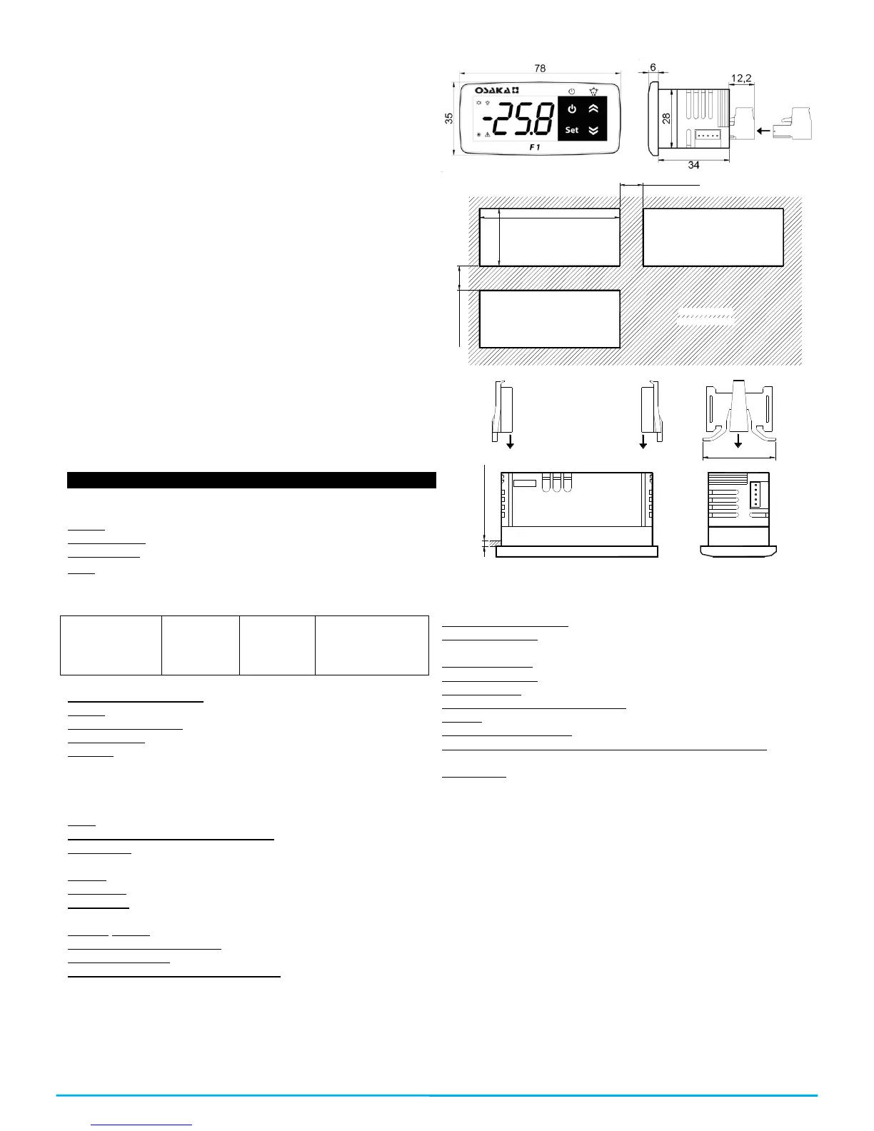
Dimensions: 78 X 35 mm, depth. 34 mm or 42.2 according to the
terminal block.
Weight: 105 g approx.
Installation: on panel, recessed 71x29mm
Connection: Inputs: Cable of 0,14…4,5mm
2
/ AWG 28...16;
Supply and output: 0,2…2,5 mm
2
/ AWG 24...14
Sealing degree: IP65 (NEMA 3S) with sealing gasket
Operating room temperature: 0 T 50 ° C
Operating humidity: <95% RH non-condensing
Storage and transportation temperature: -25 ° C T 60
7.3 – MECHANICAL DIMENSIONS, HOLES, AND MOUNTING
R E C O M M EN D E D
P AN EL C U TO U T
29
m in . 1 5 m m
m in . 1 2 m m
71
P A N E L
B RA C K E T S
34
M A X . 2 ,5 m m
7.4 – FUNCTIONAL FEATURES
Temperature regulation: ON/OFF
Defrosting control: By intervals due to the stoppage of the
compressor.
Measuring range: -50…109ºC / -58…228 ºF.
Display resolution: 1º or 0,1º (range -99.9…99.9 ºC)
Total accuracy: +*- (0,5% fs + 1 digit)
Average speed time (without filter): 130 ms.
Display: 3 red digits h 15,5mm.
Software class structure: Class A
Time maintenance of the internal clock without power supply:
Around four hours.
Compliance: 2004/108/CE (EN55022: class B; EN61000-4-2: air
8KV, contact 4KV.; EN61000-4-3: 10V/m; EN61000-4-4: power
supply 2KV relay output, 1KV inputs; EN61000-4-5: common power
supply 2KV, 1 KV\ differential mode; EN61000-4-6: 3V); Directive
2006/95/CE (EN 60730-1, EN 60730-2-9).Regulation 37/2005/CE
(EN13485 air, S, A, 2,- 50°C +90°C if it is used with NTC probe
103AT11).
 Loading...