EasyManua.ls Logo

Osaka Smart Box User Manual

Osaka Smart Box
16 pages
To Next Page IconTo Next Page
Page #1 background imageLoading...
Page #1 background image
OSAKA SMART BOX Simple Manual v1.1 Page 1
BOXED DIGITAL THERMOSTAT
FOR COLD ROOMS
Simple Manual Version 1
www.osakasolutions.com
IMPORTANT _
Read this document carefully before the installation and the
use of this device and respect all warnings; keep this
document alongside the device to solve further consults. Use
this device only as described in this document, and do not
use this device as a safety device.
To obtain further information, please consult the extensive
manual.
The device must be removed respecting the
local laws regarding the recollection of electronic
and electric devices.
1 USER’S INTERFACE _
1.1 Observations _
Anytime you want to access the parameters or do an action,
make sure beforehand that the device is ON, that the
keyboard is not locked and that there isn’t any other
procedure taking place.
1.2 Turn ON/OFF the device manually _
1. Press the key for 1 second.
1.3 The display _
During the normal operation, the display will show the
selected temperature on the P5 parameter, except during a
defrosting, in which case the display will show the selected
temperature on the d6 parameter.
1.4 See other probes’ temperature _
1. Press the key for 1 second: the display will show the
first variable that it’s available to be read.
2. Press the key or the key to select:
1. “Pb1” room temperature or air input temperature
(according to the value of the P4 parameter)
2. “Pb2” evaporator temperature
3. “Pb3” auxiliary temperature
4. “Pb4” evaporation temperature
5. “Pb5” low pressure
6. “Pb6” CPT temperature (“Pb4” in SMART BOX,
SMART BOX M, SMART BOX MD, SMART BOX
SD, SMART BOX PLUS, SMART BOX PLUS M,
SMART BOX PLUS MD and SMART BOX PLUS
SD).
7. “Pb7” auxiliary temperature 2
8. “Pb8” auxiliary temperature 3
3. Press the key to see the selected temperature.
4. Press the key again to go back to the list.
To exit the process:
5. Wait without pressing anything for 60 seconds or press the
key.
1.4 Activate / deactivate the “Turbo” mode _
1. Make sure there is no ongoing defrosting, pre-dripping and
/ or evaporator’s fan stoppage.
2. Press the key: the LED will flash, indicating its
activation.
1.5 Activate the defrosting manually _
1. Make sure that the “Turbo” mode is not running.
2. Press the key for 4 seconds.
NOTE: If the evaporator’s temperature is not below the d2
temperature, the defrosting won’t be activated.
1.6 Turn ON/OFF the led manually _
2. Press the key: THE LED will turn OFF/ON showing
the status of the light.
1.7 Activate anti-fogging resistance _
1.Press the key for 1 second: the AUX1” or “AUX2”
LED will turn on and the resistance will be activated.
Note: a configurable output must be configured as “anti-
fogging resistance”.
1.8 Activate/deactivate the auxiliary output manually _
1. Press the key for 1 second: the “AUX1” or “AUX2”
LED will turn on.
NOTE: a configurable input must be configured as “auxiliary
output”
1.9 Some values related to the electronic expansion
valve (only available in SMART BOX VEX) _
1. Press the key for 1 second: the display will show the
first variable that it’s available to be read.
2. Press the key or the key to select:
SH” (instantaneous superheating)
POS” (valve’s opening required percentage)
POr (valve’s opening instantaneous
percentage).
3. Press the key to see the data.
4. Press the key again to go back to the list.
To exit the process:
5. Wait without pressing anything for 60 seconds or press the
key.
1.10 Lock/Unlock the Keyboard _
1. Press the and keys: The display will show
Loc”/”UnL” whether it has been locked or unlocked.
1.11 Mute the warning buzzer _
1. Press any key.
Question and Answer IconNeed help?

Do you have a question about the Osaka Smart Box and is the answer not in the manual?

Osaka Smart Box Specifications

General IconGeneral
BrandOsaka
ModelSmart Box
CategoryThermostat
LanguageEnglish

Summary

User Interface Operations

Interface Observations

General advice before accessing parameters or performing actions on the device.

Manual Device Power Control

Instructions for manually switching the device on or off using the power button.

Display Information

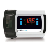
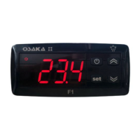
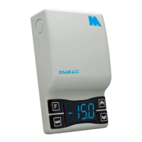
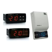
Explanation of what information is shown on the device's display during normal operation and defrosting.

Viewing Probe Temperatures

How to view temperatures from different probes (room, evaporator, auxiliary) using the interface.

Turbo Mode Activation

Procedure to activate or deactivate the "Turbo" mode for enhanced cooling performance.

Manual Defrosting

Steps to manually initiate a defrosting cycle for the evaporator.

Manual LED Control

How to manually control the device's LED indicator for lighting functions.

Anti-fogging Resistance Activation

Method to activate the anti-fogging resistance using the auxiliary output.

Manual Auxiliary Output Control

Instructions for manually controlling an auxiliary output via the AUX key.

Electronic Expansion Valve Parameters

How to view parameters like superheating and valve opening for the electronic expansion valve.

Keyboard Lock/Unlock

Procedure to lock or unlock the device's keyboard to prevent unintended changes.

Warning Buzzer Muting

How to silence the warning buzzer by pressing any key.

Humidity-Based Operation

Activating Humidity Operation

How to enable and understand the device's operation based on high or low humidity levels.

Checking Active Operation Mode

Method to check if the device is currently operating in high or low humidity mode.

HACCP Operation and Alarms

Viewing HACCP Alarms

How to view recorded alarms, including temperature, door, and power failure alerts, with timestamps.

Deleting HACCP Alarms

Procedure to clear recorded HACCP alarms and data logger error codes.

Data Logging (EN 12830)

HACCP Data Logging Mode

Information on the always-activated HACCP data logging operation mode.

Service Data Logging Mode

Steps to activate the data logging operation mode for service purposes.

Data Logger Error Information

How to display errors related to the data logger, such as SD card issues or battery errors.

Compressor Operation Hours

Checking Compressor Hours

How to check the accumulated running hours for compressor 1 and compressor 2.

Deleting Compressor Hours

Procedure to reset and delete the recorded operation hours of the compressor(s).

Device Settings Configuration

Configure Date, Hour, and Day

Guide to setting the real-time clock, including year, month, day, hour, and day of the week.

Set Regulation Set Point

How to set and adjust the main temperature regulation set point for the device.

Accessing Parameters

Instructions on how to access and navigate through the device's various configuration parameters.

Factory Reset

Steps to restore the device's settings to their original factory default values.

Signals and Device Indications

LED Signals

Explanation of the various LEDs on the device and their corresponding meanings.

Error Code Indications

Interpretation of error codes (Loc, dEF) displayed by the device indicating specific states or issues.

SD Card Status Indications

Understanding the status of the SD card based on the color and state of its indicator LED.

Alarms and Error Codes

Alarm Codes and Meanings

Comprehensive list and explanation of all possible alarm codes and their meanings.

Error Codes and Meanings

Detailed list and explanation of error codes related to probes, SD card, and internal system functions.

Technical Data

Device Specifications

Detailed specifications of the device's construction, dimensions, connections, and operating environment.

Parameter List

Regulation Set Point Parameters

Parameters related to setting and adjusting the main temperature control point.

Analog Input Parameters

Parameters for calibrating and configuring analog sensor inputs like temperature and pressure.

Regulation Parameters

Parameters governing the device's regulation behavior, including differentials and limits.

Electronic Expansion Valve Parameters (VEX)

Specific parameters for controlling the electronic expansion valve in VEX models.

Compressor Protection Parameters

Parameters for protecting the compressor against various fault conditions and operational limits.

Defrosting Parameters

Parameters that control the timing, type, and duration of defrosting cycles.

Temperature Alarm Parameters

Parameters defining set points and delays for high and low temperature alarms.

Fan Operation Parameters

Parameters controlling the operation and timing of evaporator and condenser fans.

Digital Input Configuration

Parameters for configuring the functions of various digital inputs, like door switches.

Digital Output Management

Parameters for managing the functions of digital outputs, such as alarms or lights.

Real Time Clock Configuration

Parameter to enable and manage the device's internal real-time clock functionality.

Energy Saving Mode Parameters

Parameters for configuring the energy-saving mode, including activation hours and duration.

Real Time Defrosting Parameters

Parameters for setting activation times for multiple daily defrosting cycles.

Data Logging Extension Parameters

Parameters related to data logging intervals, duration, and probe enabling.

Modbus RS-485 Configuration

Parameters for configuring the Modbus communication settings, including address and baud rate.

Dimensions and Installation

Device Physical Dimensions

Physical dimensions of the SMART BOX device presented in millimeters and inches.

Installation Guidelines

Guidelines and precautions for installing the device in suitable environments and locations.

Electrical Diagrams

SMART BOX Electrical Diagram

Electrical wiring diagram for the standard OSAKA SMART BOX model.

SMART BOX PLUS Electrical Diagram

Electrical wiring diagram for the OSAKA SMART BOX PLUS model.

SMART BOX M Electrical Diagram

Electrical wiring diagram for the OSAKA SMART BOX M model.

SMART BOX MD Electrical Diagram

Electrical wiring diagram for the OSAKA SMART BOX MD model.

SMART BOX PLUS M Electrical Diagram

Electrical wiring diagram for the OSAKA SMART BOX PLUS M model.

SMART BOX PLUS MD Electrical Diagram

Electrical wiring diagram for the OSAKA SMART BOX PLUS MD model.

SMART BOX VEX Electrical Diagram

Electrical wiring diagram for the OSAKA SMART BOX VEX model, including expansion valve control.

SMART BOX VEX M Electrical Diagram

Electrical wiring diagram for the OSAKA SMART BOX VEX M model.

SMART BOX VEX MD Electrical Diagram

Electrical wiring diagram for the OSAKA SMART BOX VEX MD model.

SMART BOX SD Electrical Diagram

Electrical wiring diagram for the OSAKA SMART BOX SD model with data logging.

SMART BOX PLUS SD Electrical Diagram

Electrical wiring diagram for the OSAKA SMART BOX PLUS SD model with data logging.

Electric Connection and Warranty

Additional Electric Connection Info

Important considerations and precautions for connecting the device electrically.

Warranty and Repair Information

Information regarding the product's warranty period and procedures for repairs or replacements.

Related product manuals