OSAKA – F 1 – User’s Manual – v1 – PAG. 9
“A” Alarm configuration parameters
Temperature alarm
type:
1 = Absolute for Pr1
probe with visualization
in the display (Hi-Lo).
2 = Relative for Pr1
probe with visualization
in the display (Hi-Lo).
3, 4 = DO NOT USE
5 = Absolute for Pr1
probe without display’s
visualization.
6 = Relative for Pr1
probe without display’s
visualization.
7, 8 = DO NOT USE
1 / 2 / 3 / 4 / 5 /
6 / 7 / 8
Alarm set for high
temperatures.
Alarm set for low
temperatures.
Temperature alarm
differential.
oF ÷ 0.01 ÷
9.59 (min.sec)
÷ 99.5
(min.sec)
Alarms connection
delay when turning on.
oF ÷ 0.01 ÷
9.59 (hrs.min)
÷ 99.5
(hrs.min)
Temperature alarm
delay after the
defrosting and locking
of the display during
the defrosting.
oF ÷ 0.01 ÷
9.59 (hrs.min)
÷ 99.5
(hrs.min)
oF ÷ 0.01 ÷
9.59 (min.sec)
÷ 99.5
(min.sec)
“t” – Keyboard configuration parameters.
“F” key operation
mode.
oF = no function
1= DO NOT USE
2= Select economic
mode.
3= Start / Stop
(Stand-by)
4 = DO NOT USE
Down/Aux key
operation mode (see
“t.UF”)
Automatic keyboard
locking.
oF ÷ 0.01 ÷
9.59 (min.sec)
÷ 30.0
(min.sec)
Set Point visibility with
quick procedure with
SET key
oF = none
1 = SP
2 = SPE
3 = SP and SPE
4 = Active SP
5, 6 = DO NOT USE
Password to access
the operational
parameters.
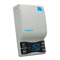
6 – ERROS, MAINTENANCE AND WARRANTY
The relative probe can
be broken (E) or in
short-circuit (-E), or have
a value that is out of the
programmed range.
Verify the connection of
the probe to the
controller and verify the
correct operation of the
probe (it is useful to
have the ohm values of
the probes)
Possible anomaly in the
EEPROM memory.
Press the SET key. Turn
off and turn on the
controller.
Fatal Error of the
controller’s memory.
Replace the controller or
send it for a possible
reparation.
Delay at the start after power supplying the
controller.
Ongoing digital input alarm.
Active defrosting, it shows if “d.dL” =Lb
Defrosting finished, recovering cold if
“d.dL” = Lb