OSAKA – F 1 – User’s Manual – v1 – PAG. 3
4-CUSTOMIZING PARAMETERS WITH / WITHOUT PASSWORD
The controller allows you to protect only some parameters with
password and the other ones without it, so that the user has access
to the parameters that he might need, without letting you access
the entirety of parameters that belong to the technician or
manufacturer.
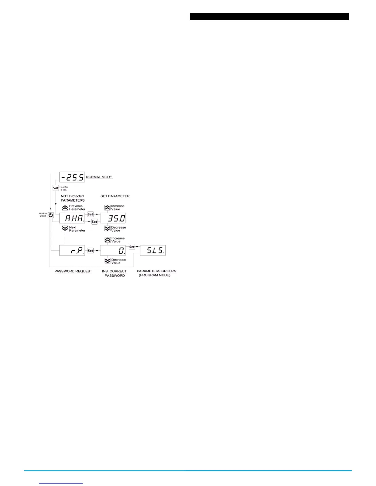
Method to select the programming level of the parameters:
Access the programming through the password and select the
parameter that you want to program without password. If the SET
led is flashing it means that the parameter is programmable only
with the password, i.e. it is protected. And if the led is lit and fixed it
indicates that the parameter has direct access without a password.
To modify the parameter’s visibility level keep the SET key pressed
for 5 seconds, and when the parameter starts flashing, press the
UP key without releasing the SET key, and you will be able to see
that the led’s state has changed.
The SET led will change its state indicating the new access level to
the parameter (protected, flashing led) and (direct access without
password, fixed led)
When entering the parameter’s menu we will first see the user’s
level (not protected) parameters) and then the protected ones by
introducing the password when the controller shows “r.P”
2.5 – RESTORATION OF INITIAL PARAMETERS
The controller has a mode where you can reset all the parameters
to the parameters by default from the manufacturer.
To go back to the manufacturer’s values or the parameter’s values
by default you only have to activate the protection through
password and once that is activated and when the display shows
“r.P”, enter the password -48.
Once the password is confirmed with the SET key, the display will
show for 2 seconds “---”. When the controller resets the
parameters, it makes a little testing and puts all the parameters
back at their default value.
2.6 – KEYBOARD LOCKING FUNCTION
It is possible to completely block all the keys. This function is useful
when the public has access to the control and you want to prevent
any handling. The keyboard locking function is activated by
programming the “t.Lo” parameter to a different OF value. The
programmed value in the “t.Lo” parameter is the amount of time
that the thermostat allows access to the keyboard, thus, after
surpassing this amount of time the thermostat will remain blocked.
By pressing any of the thermostat’s keys it will show “Ln” to inform
that the locking is protected (blocked).
To unlock the keyboard press “SET+UP” for 5 seconds and the
display will show “LF” and all the keyboards functions will be
operational again.
3.1 – USAGE WARNING
The units are manufactured as measurement and regulation
devices in compliance with EN60730-1 for a functioning of up to
2000m of altitude.
The use of these controllers in applications that are not specifically
subject to the aforementioned law must foresee all necessary
measuring and protecting adaptations.
The controllers must be adequately protected and out of reach from
liquids, dust, grease and dirtiness. They must only be accessible
with the use of a tool or safe system (except the front).
The controllers can NOT be used in environments with a dangerous
atmosphere (inflammable or explosive) without adequate
protection.
Be reminded that the installer must ensure that the norm for
electromagnetic compatibility is respected after the implantation in
the equipment’s installation, eventually using the right filters if it is
needed.
In case of failure or malfunction of the control and measuring
controllers that can create dangerous situations or damage to
people, things, animals or products (defrost food or change in its
ideal state), it is recalled that the facility should be equipped with
electronic devices or electromechanical safety and warning system.
Protective devices should be placed outside the control and
measuring controllers, responding to specific safety requirements
that are covered by the norm of the product or that common sense
might suggest.
For your own safety, it is highly recommended fulfilling the
instructions provided above.
3.2 – MECHANICAL ASSEMBLING
The 78x35mm thermostat’s housing is designed to be wall-
mounted.
Make a hole of 71x29mm and insert the controller fixing it with the
clamps that are included.
It is recommended to place the protection seal to obtain more
protection and tightness.
Avoid placing the thermostat in places exposed to high humidity or
dust, this can cause condensation or insertion of conductive
particles or substances. Ensure that you have an adequate
ventilation and avoid installing in indoor sealed boxes or areas
where the temperature exceeds the technical specifications of the
controller. Avoid installing the cables and power supply together
with the probe and install it away from devices that can generate
disturbances (electrical noise) such as motors, fans, inverters,
automatic gates, contactors, relays, solenoids, etc...
3.3 – ELECTRICAL CONNECTION
The thermostat is designed for the permanent connection between
devices; no switch is equipped with internal devices of potency for
over currents or overvoltage. Thus it is recommended to install a
general / magnet thermal (circuit breaker) switch as close as
possible to the controller and of easy access as a safety measure.
Be reminded that you must use the appropriate wire to the isolation
of voltage, current, temperature and electrical normative of the
venue. In addition you have to separate the probe signaling wires
from the supply and power wires as much as possible so that you
can avoid possible electrical noises, electromagnetic inductions,
which in some cases could be diminish or voided with RC filters,
ferritic, supply, resistors, etc. ... the use of wires with anti-parasitic
mesh and this mesh is recommended to connect on one side to
take ground
It is recommended to check that the equipment settings are
appropriate to the application before connecting wires actuators,
loads on the output relays in order to prevent malfunctions or
damage.
 Loading...