OSAKA - F 200 / F 300 / TSF 200 / TSF 300 / M3 - User Manual - V.2 - PAG. 1
DIGITAL THERMOSTAT
REFRIGERATION
F 200 / F 300
TSF 200 / TSF 300
M3
User manual – Version 2
www.osakasolutions.com
In this manual are the information necessary
for proper installation and instruction for use
and maintenance of the product, it is
recommended to read carefully and keep it.
To prevent erratic operation or malfunction of
the THERMOSTAT that can create dangerous
situations, damage to persons, things or
animals, please remember that the facility must meet and be
aware of the safety systems annexes necessary to ensure their
safety.
OSAKA SOLUTIONS or their legal representatives are not
responsible for misuse of THERMOSTAT or not conforming to
the characteristics of the THERMOSTAT.
Index
QUICK SELECTION SET POINT
STANDARD PROGRAMMING PARAMETERS
PROTECTED PARAMETERS BY PASSWORD
CUSTOM PROGRAMMING PARAMETERS (LEVELS OF
PROGRAMMING PARAMETERS)
RESTORE FACTORY SETTINGS
KEYBOARD LOCK FUNCTION
WARNING FOR INSTALLATION AND USE
ELECTRICAL CONNECTIONS
ELECTRICAL WIRING DIAGRAM
OPERATION
FUNCTION ON / STAND-BY
SETTINGS OF INPUTS PROBES AND DISPLAY
OUTPUTS SETUP FOR RELAYS AND BUZZER
ACTIVE SET POINT SELECTION
COMPRESSOR PROTECTION FUNCTION AND DELAY
TO START
DEFROST CONTROL
AUTOMATIC START DEFROST
MANUAL DEFROST
END OF DEFROST
DISPLAY LOCK ON DEFROST MODE
EXTERNAL ALARM DIGITAL INPUT
4.11
4.12
4.12.1
4.12.2
4.12.3
OPERATION OF KEY “F” / AND “DOWN / AUX”
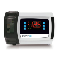
ACCESSORIES
CONFIGURATION PARAMETERS WITH “USB KEY”
REMOTE VIEWING "X2"
RS485 SERIAL COMMUNICATION WITH "CONV-TTL
RS"
PROGRAMMABLE PARAMETERS LIST
TROUBLESHOOTING, MAINTENANCE AND
WARRANTY
MECHANICAL FEATURES
FUNCTIONAL FEATURES
MECHANICAL DIMENSION AND SUBJECTION
1.1 – GENERAL DESCRIPTION
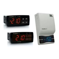
The F 200 / F 300 / TSF 200 / TSF 300 / M3 are microprocessor
digital thermostats, are suitable for refrigeration temperature with
ON / OFF control and intervals time for defrost, to regulate
temperature or continuous operating time compressor, electric
heater or hot gas for investment cycle. The device is equipped with
optimization functions and special defrosting functions used for
energy saving control.
Thermostats, depending on the model, available from 2 to 3 relay
outputs and 2 to 3 inputs for temperature sensors PTC or NTC and
also an internal buzzer for acoustic signalling ALARM and
programming.
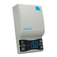
Models F 200 / F 300 / TSF 200 / TSF 300 / M3 differ from other
standard models on the design and screen system keyboard.
1.2 – FRONT PANEL DESCRIPTION
Front Panel F 200 / F 300