OSAKA - F 200 / F 300 / TSF 200 / TSF 300 / M3 - User Manual - V.2 - PAG. 9
The device can signal an external alarm in device by activating the
digital input with the function programmed as "i.Fi" = 4 or 9.
Contemporaneously with the signaling configured alarm (buzzer
and / or output), the device signals the alarm by activating the
ALARM LED display and its display label AL alternately with the
variable set in par. "I.dS".
The mode "i.Fi” = 4 does not operate with no action on the control
output, while the mode "i.Fi" = 9 provides disabling all control
outputs in the intervention of the digital input.
4.10.3 – OPEN DOOR ALARM
The device may signal a door alarm by activating the digital input
with the function programmed as "i.Fi" = 5 or 6.
In activating the digital input the device indicates that door is open
through viewing the display oP alternately with the variable set in
parameter label. "I.dS".
After the delay programmed in par. "A.oA" the device notes the
alarm through the activation of the configured device (buzzer and /
or output), activating the ALARM LED is continuous with message
display oP.
The intervention of the open door alarm is also reactivated when
the output is inhibited (fan + fan or compressor).
4.11 – OPERATION OF KEY “F” / AND “DOWN / AUX”
The key "F" or is defined by the "t.UF" parameter while the
keyboard function "DOWN / AUX" can be defined by the "t.Fb" the
two parameter included in settings "t".
Both parameters have the same possibilities and can be configured
for the following functions:
= OF - No Function
= 1 - Pressing the button for at least 1 second to turn on / off the
auxiliary output from configuring ("o.Fo" = 2) parameter.
= 2 - Press the button for at least 1 second to enable / disable a
continuous cycle.
= 3 - Pressing the button for at least 1 second, one of 2 set point
stored in rotation is selected. After selection, the display will flash
for approximately 1 second showing the value of the active set
point (SP or SP 2)
= 4 - Press the button for at least 1 second instrument status from
on to standby and vice versa is changed.
4.12 - ACCESSORIES
The device is equipped with a 5-pin connector for connecting an
accessory described below.
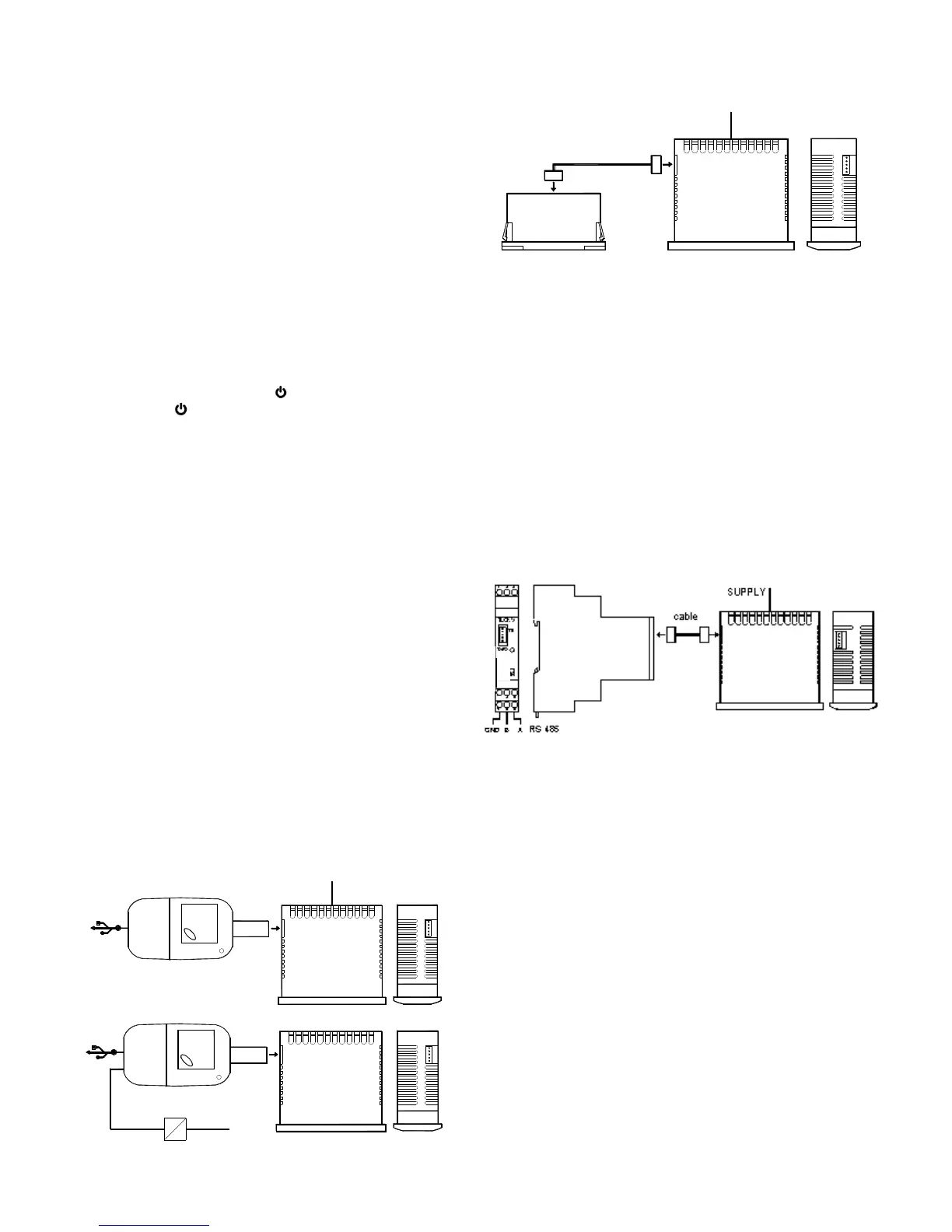
4.12.1 – CONFIGURATION PARAMETERS WITH “USB KEY”
The device has a connector that allows you to transfer the
operating parameters from the "KEY USB" device equipped with a
5-pin connector. The "KEY USB" device is used for serial
programming of devices must have the same configuration
parameters, or to save a copy of the programming device and to
transfer it quickly. The device has a USB input, allowing connection
to a PC, with which, through the software configuration "Universal
Conf" or "Osaka Set Up" is possible to configure operating
parameters.
Refer to the user manual regarding X2 device for more information.
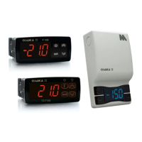
4.12.3 - RS485 SERIAL COMMUNICATION WITH "CONV-TTL
RS"
Through RS CONV-TTL device can connect the device to your
computer to a network serial RS485 that are integrated into other
equipment (controller or PLC) and is directed to a personal
computer used as plant supervisor communication.
The protocol software is suited to computer MODBUS RTU type
widely used in several PLC and supervision programs available on
the market.
If the equipment is used with CONV-TTL RS, program par. "T.Ad"
device management.
Therefore put in this parameter, a different number than the others,
from 1 to 255.
The transmission speed (baud-rate) series is not adjustable and is
fixed at 9600 baud.
CONV-TTL converter RS is powered directly from your device.
Consult the user manual on the CONV-TTL RS device for more
information.
 Loading...