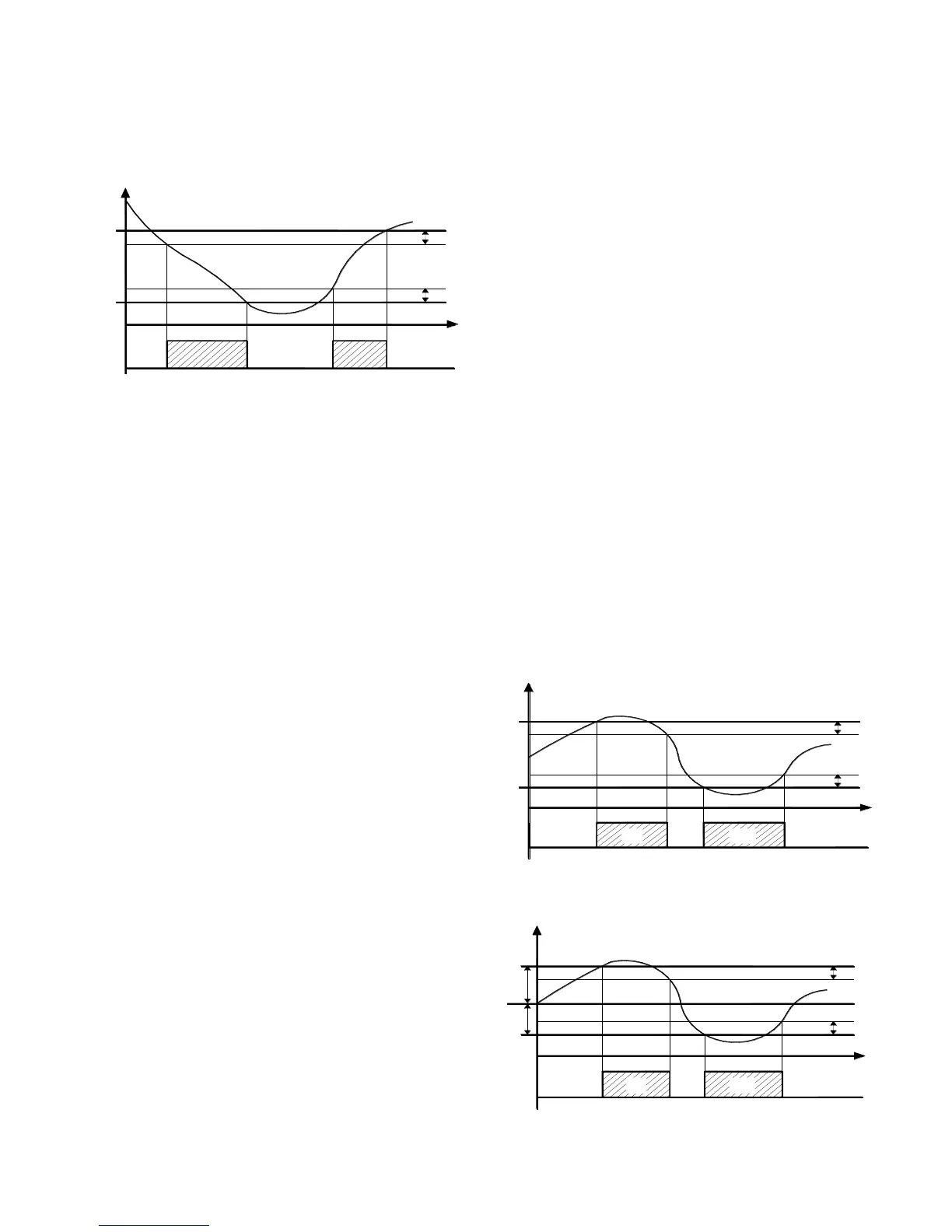
You can set the fan off when the temperature measured by the
evaporator probe is higher than programmed in the "F.FL"
parameter (temperature too high) or where it is less than the value
programmed in the "F.LF" parameter (very low temperature).
Associated with these parameters is a programmable differential in
the "F.dF" parameter.
Note: You must pay special attention to the proper use of the
functions of fan control based on temperature as a typical
application of a typical refrigeration evaporator fan stops for heat
exchange.
It is recalled that the operation of the evaporator fan can be
conditioned to the "open door" function of the digital inputs.
4.10 – ALARM FUNCTIONS
Alarm conditions controllers are:
- Probe Error: "E1", "-E1", "E2," -E2"
- Temperature alarm: "Hi", "Lo"
- External alarm "AL"
- Alarm door open: "oP"
The alarm function is displayed the ALARM LED on the internal
buzzer, set by the par. "O.bu" or on the desired output is set by par.
"O.o1" "o.o2".
Buzzer sounds on alarm but can be disconnected the par. "O.bu" =
1 or 3, and after ringing can be deactivated by pressing a key. The
alarm output can point to the following schedule settings of the
output.
The possible selection of these parameters for the operation of
alarm signal are:
= At – When you want the output to be activated in alarm condition
and can be turned off (by keypad alarm) manually.
= AL – When you want the output to be active in alarm
CONDITION but can not be turned off manually or is only when the
alarm condition is cancelled. (Typical Application one bright signal).
= An – When you want the output to be active in alarm conditions
and keeps on even if the alarm condition disappears (alarm
memory) Deactivation (recognition memorized alarm) can be
removed manually by pressing any key when the alarm is over.
= -At – When the operation described as "At" with inverse logic is
desired. (output activated in normal condition and disabled in alarm
status).
= -AL – When the operation described as "AL" but with function
logic reversed is desired.(output activated in normal and disabled in
alarm status)
=-An – When considering the operation described as "An" but with
inverse logic operation (output activated in normal and disabled in
alarm status)
The unit has the option of having the function of activating the
alarm memory "A.tA" parameter.
If "A.tA" = Of the device cancels the alarm signal to alarm
conditions cease, but if programed = On alarm conditions are also
recorded but keeps flashing ALARM LED and indicates that an
alarm was verified.
To cancel the alarm memory signaling just press any key.
It is recalled that if the operation of a memory alarm output (o = An-
An) is desired, you must program the "A.tA" = on parameter.
4.10.1 – ALARM FUNCTIONS
The alarm function is a function of temperature reading from the
probe, and the type of programmed alarm, parameter. "A.Ay" and
the alarm set point, par. "A.HA" (maximum alarm) and "A.LA"
(minimum alarm).
Through the "A.Ay" parameter you can specify whether the alarm
set "A.HA" and "A.LA" should be considered absolute or relative to
the active Set Point, whether to display in the message display Hi
(High alarm ) or Lo (low alarm) when entering alarm or not.
Depending on the operation by the par "A.Ay" considered can be
programmed with the following value:
= 1: Absolute reference to Pr1 with visualization. Display (Hi - Lo)
= 2: Relative with reference to Pr1 visualization. Display (Hi - Lo)
= 3 Absolute concerning the probe Pr2 configured as "ancillary" to
display. Display (Hi - Lo)
= 4: Relative reference to the probe Pr2 configured as "ancillary" to
display. Display (Hi-Lo)
= 5: Absolute concerning Pr1 no display
= 6: Relative concerning Pr1 no display
= 7: Absolute reference to the "auxiliary" probe without display
= 8: Relative reference to the "auxiliary" probe without display
By some parameters may delay activation, if the situation is
cancelled recovering optimal conditions, without becoming alarm.
These parameters are:
“A.PA” – delay time the alarm to get power and turn on the
regulation, in case you are in alarm.
“A.dA” – time delay after a defrost (A. maximum) or after a
continuous cycle (A. Min).
“A.At” – delay time of the performance of temperature alarm.
Temperature alarms are enabled at the end of exclusion time and
is activated after the "A.At" when the temperature measured by the
probe exceeds or falls below the alarm thresholds respective
maximum and minimum.
The differential alarm will be the same set in parameters "A.HA"
and "A.LA" if alarms are absolute ("A.Ay" = 1, 3, 5, 7).
 Loading...