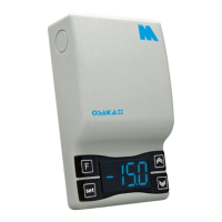
4.1 – FUNCTION ON / STAND-BY
The thermostat, once fed, can make 2 states:
- ON: means that the driver is running and acting on the basis of
planned control.
- STAND-BY: means that the control does not act, stop. (The
display illuminates the LED Stand-by).
Moving from Stand-by to ON is exactly equivalent to when the
device is connected to supply. If a power failure occurs when power
returns, the system is always put in the condition that it was before
the interruption.
Mode ON / Stand-by can be selected:
- Using the key or "F" pressed for 3 sec Lets stop to change gear.
- Use the DOWN key for 3 sec If the par. "T.Fb" = 4
- Using the digital input if par. "I.Fi" = 10
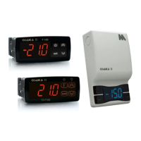
4.2 – SETTINGS OF INPUTS PROBES AND DISPLAY
By the par. "I.SE" is selected if the probe you want to use is the
type KTY81 PTC-121 (Pt) or NTC 103AT-2 (nt).
With the par. "I.uP" is selected if the unit of measure to use is the
temperature in degrees Celsius (Standard) or Fahrenheit (USA)
(C0 = ° C / 1 ° (no decimal); C1 = ° C / 0.1 ° (with decimal); F0 = ° F
/ 1 °, F1 = ° F / 0.1 °).
The unit allows the calibration of the probes, which can be used for
recalibration of the equipment according to the needs of the
application through the par. "I.C1" (Pr1 entry), "i.C2" (Pr2 entry).
The par. "I.P2" to select the use of Pr2 entry, as follows:
= EP - Evaporator Probe (EP): Evaporator probe Probe (EP): the
probe functions as described below to control defrost and
evaporator fans.
= Au - Auxiliar probe (Au)
= DG – Digital Input (dG)
If the Pr2 and / or Pr3 input is not used, program it as "i.P2" and
"i.P3" = Of.
By the par. "I.Ft" it is possible to filter software on the extent of the
value of the input, so we can reduce the sensitivity and rapid
temperature change (rise time).
Through the par. "I.dS" you can set the normal display of the
display may be the measure of Pr1 probe (P1), the measurement of
the probe Pr2 (P2), the measure of Pr3 probe (P3) regulating the
Set Point active (SP), or you can still have the display off (oF).
If you see one of the measures by the par ("i.dS" = P1, P2, P3) par.
"I.CU" lets put an offset that is applied to display only the variable
(all regulatory controls are always made according to the
correct parameter measurement calibration).
Regardless of the value set in par. "I.dS" you can display all the
measured variables and rotating operation by pressing and
releasing the or "F" key.
The display will show alternately the code that identifies the
variable (see below) and its value.
The variables are as follows:
"Pr1" - Measuring probe Pr1
"Pr2" - Measuring probe Pr2
"Pr3" - Measuring probe Pr3
"Lt" - preset minimum temperature Pr1
"Ht" - Maximum temperature Pr1 memorized
The values of minimum and maximum peak Pr1 not saved to the
lack of supply and may be reset using the DOWN key, pressing it
for 3 sec. during peak viewing. After 3 seconds, the display will
show "---" for a moment and tell cancellation and taken as
maximum temperature measured at that time.
To exit the display mode of the variable will automatically in about
15 seconds after pressing the button or "F".
Note that the display of the probe Pr1 can also change the display
through the display lock function defrosting by the par. "D.dL" (see
the function. "Defrost").
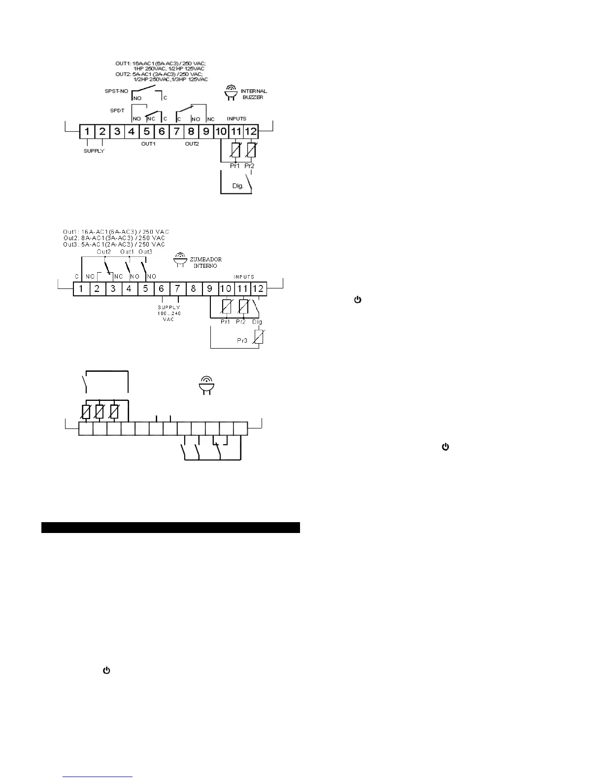
4.3 – DIGITAL INPUT SETUP
The Pr2/Pr3 input (Pr2 in F200/TSF200 and Pr3 in
F300/TSF300/M3) can be configured as digital input voltage free
contact. To use the digital input must be set par. ("I.P2" = dG. On
F200/TSF200 "i.P3" = dG. On F300/TSF300/M3). The function for
that dig input will be scheduled in the "i.Fi" parameter and the
possible delay in the schedule "i.ti" parameter.
The "i.Fi" parameter or digital input can be programmed for:
= 0 – Inactive digital input (no function)
= 1 – Start defrost with contact normally open: on closing the input
(and after time "i.ti") a defrost cycle is activated.
= 2 – End of defrost with contact normally open: on closing the
input (and after the time "i.ti") the defrosting progress ends.
= 3 – Enabling Continuous cycle with contact normally open: on
closing the input (and after the time "i.ti") activates a continuous
cycle.
= 4 - Signalling of external alarm. When digital contact is closed
and after the time set in "i.ti" the display will alternately AL with the
measured temperature.
= 5 – Door opening with fan block with contact normally open: on
closing the input (and after the time "i.ti") fan stop, device shows on
display Op and alternating with the variable set in par. "I.dS". In
this mode the action of the digital input is always active after the
time set in par. "A.oA", after which the alarm is activated to signal
that the door is open and the fan OFF.
 Loading...