OSAKA - F 200 / F 300 / TSF 200 / TSF 300 / M3 - User Manual - V.2 - PAG. 3
parameters needed, without access to all parameters that are
specific of technical or machine manufacturer.
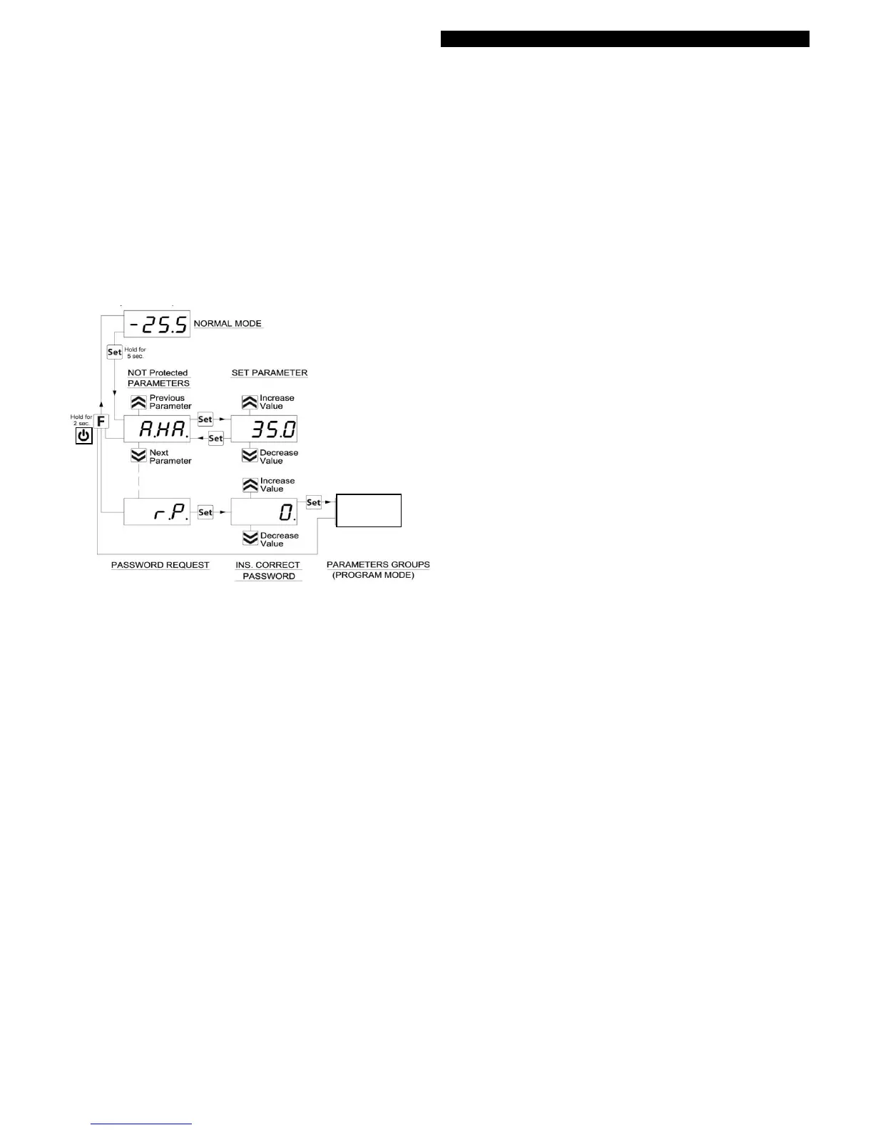
Method to select the level of programming parameters:
Access programming through password and select the parameter
to be programmed without password. If the SET LED flashes
means that the parameter is programmable only with password
protected, and if the LED is fixed indicates that the parameter is
direct access without password.
To modify the visibility level parameter jointly press "Set + Up"
keys.
The LED Set will change status, indicating the new access level
parameter (protected, flashing led) and (direct access without
password, fixed led).
Upon entering the menu, the first parameters to visualize are user
level parameters (unprotected) and then (protected) by entering the
password when the computer shows "rP"
2.5 – RESTORE FACTORY SETUP PARAMETERS
The device has a mode parameter reset to factory programmed
values.
To return to the factory settings or default values of the parameters
is sufficient to activate the password protection and once activated
when the display set "rP" enter the password -48.
After confirming the password with the SET button for 2 seconds
display will show "---" when the computer performs the reset of the
parameters, does a little testing and put all settings to default
values.
2.6 - KEYBOARD LOCK FUNCTION
It is possible to completely lock the keys. Such a function is useful
when the control is accessible to the public and you want to prevent
tampering. The key lock function is activated by setting the "t.Lo"
parameter to a value of OF.
The value set in parameter "T.Lo" is the time that the thermostat
allows access to the keyboard and after passing this time the
thermostat is locked.
Pressing any key displays the thermostat "Ln" to inform the lock is
activated.
To unlock the keyboard press "Set + Up" for 5 sec., the display will
show "LF" and all keyboard functions again become operational.
3.1 – PROPER USE
The devices are made as measuring and regulating equipment in
accordance with EN EN60730-1 norm for operation up to an
altitude of 2000 mts.
The use of equipment for standard applications not expressly
provided in norm cited above, should provide all measurement and
adjustments necessary protection.
The equipment must be adequately protected and away from
liquids, dust, grease and dirt. They must be accessible only with the
use of a right tool and safety system (except the front).
The devices can NOT be used in dangerous environments
(flammable or explosive) without adequate protection.
It is recalled that the installer must ensure that the norm for
electromagnetic compatibility is respected after implantation in the
installation of equipment, eventually using the right filters if is
needed.
In case of failure or malfunction of measuring and control
equipment that can create dangerous situations or damage to
persons, things, animals or products (defrost food or changes in
their ideal state), it is recalled that the facility should be equipped
with electronic devices or electromechanical safety and warning
system.
They should be placed outside the measuring and control
equipments, possible protective devices, responding to specific
safety requirements that are covered by the norm of the product or
suggest the common sense.
For your own safety, is highly recommended fulfilling the
instructions provided above.
3.2 – MECHANICAL ASSEMBLY
The thermostats are designed for wall mounting or wall using the
holes in the plastic and predisposed accessible after removing the
front.
Once the equipment is installed is recommended to close the front
cover.
Avoid placing the thermostat in place exposed to high humidity or
dust, this can cause condensation or introduction of conductive
particles or substances. Ensure that the computer has adequate
ventilation and avoid installing indoor sealed boxes or areas where
the temperature exceeds the specifications of the device. Avoid
installing the cables and power supply together with the probe out
and install equipment that can generate disturbances (electrical
noise) as motors, fans, inverters, automatic gates, contactors,
relays, solenoids, etc.…
3.3 – ELECTRICAL CONNECTIONS
The thermostat is designed for permanent connection between
devices, no switch is equipped with internal devices or power on
over currents or voltages. It is therefore recommended to install a
general safety thermal / isolator switch / device magneto device as
close and easy access to cut if necessary, as a security . Are
reminded that you must use appropriate cable to own isolation
voltage, current, temperature and local electrical codes should also
separate the signal cables from the power probe and power as far
as possible in order avoid possible electrical noise, electromagnetic
induction, which in some cases could be diminished or cancelled
with RC filters, ferritic, supply, varistors, etc. ... the use of cables
with antiparasitic mesh and this mesh is recommended to connect
on one side to take ground.
It is recommended to check that the equipment settings are
appropriate to the application before connecting wires actuators,
loads on the output relays in order to prevent malfunctions or
damage.
 Loading...