6.2 - CLEANING
We recommend cleaning with a damp cloth only without detergent
or detergent.
6.3 – WARRANTY AND REPAIR
This device has a guarantee in form of repair or replacement by
manufacturing defects in materials of 12 months from the date of
purchase.
OSAKA SOLUTIONS automatically void this guarantee and is not
liable for any damages deriving from:
- Use, installation, or use and handling undue, others than
those described above and, in particular, differs from the
safety requirements established by the regulations.
- Use in applications, machines or electrical panels that do
not provide adequate protection against liquids, dust,
grease and electric shocks to the installation conditions
made.
- The inexperienced handling, and / or alteration of the
product.
- The installation / use in applications, machines or
electrical panels do not comply with the valid norm.
In case of defective product under warranty or out of that period, it
should contact the post sales service to perform the necessary
steps. Request document repair "RMA" (by mail or fax) and
complete it, is necessary send the RMA and the device to SAT
OSAKA by method prepaid.
7.1 – ELECTRICAL FEATURES
Supply: 12…24 VAC/DC (F 100) - 100...240 VAC +/- 10%
Frequency AC: 50/60 Hz
Consumption: 4 VA
Input /i: 1 input for temperature sensor NTC (103AT-2, 10 K Ω @
25 °C) o PTC (KTY 81-121, 990 Ω @ 25° C)
Output: 1 Relay SPDT
M1: 8A-AC1 (3A-AC3) / 250 VAC
F 100 / TSF 100: 16A-AC1 (9A-AC3) / 250 VAC
Electrical life relay output: 100000 op.
Power supply: EN 60730-1 type 1.B
Overvoltage category: II
Device Class: Class II
Isolation: Isolated by piece low voltage (power 115/230 V and relay
outputs); and part low voltage inputs; Electrically isolated between
output and supply.
7.2 - MECHANICAL FEATURES
Carcase: Plastic self-extinguishing UL 94 V0
Category of resistance to heat and fire: D
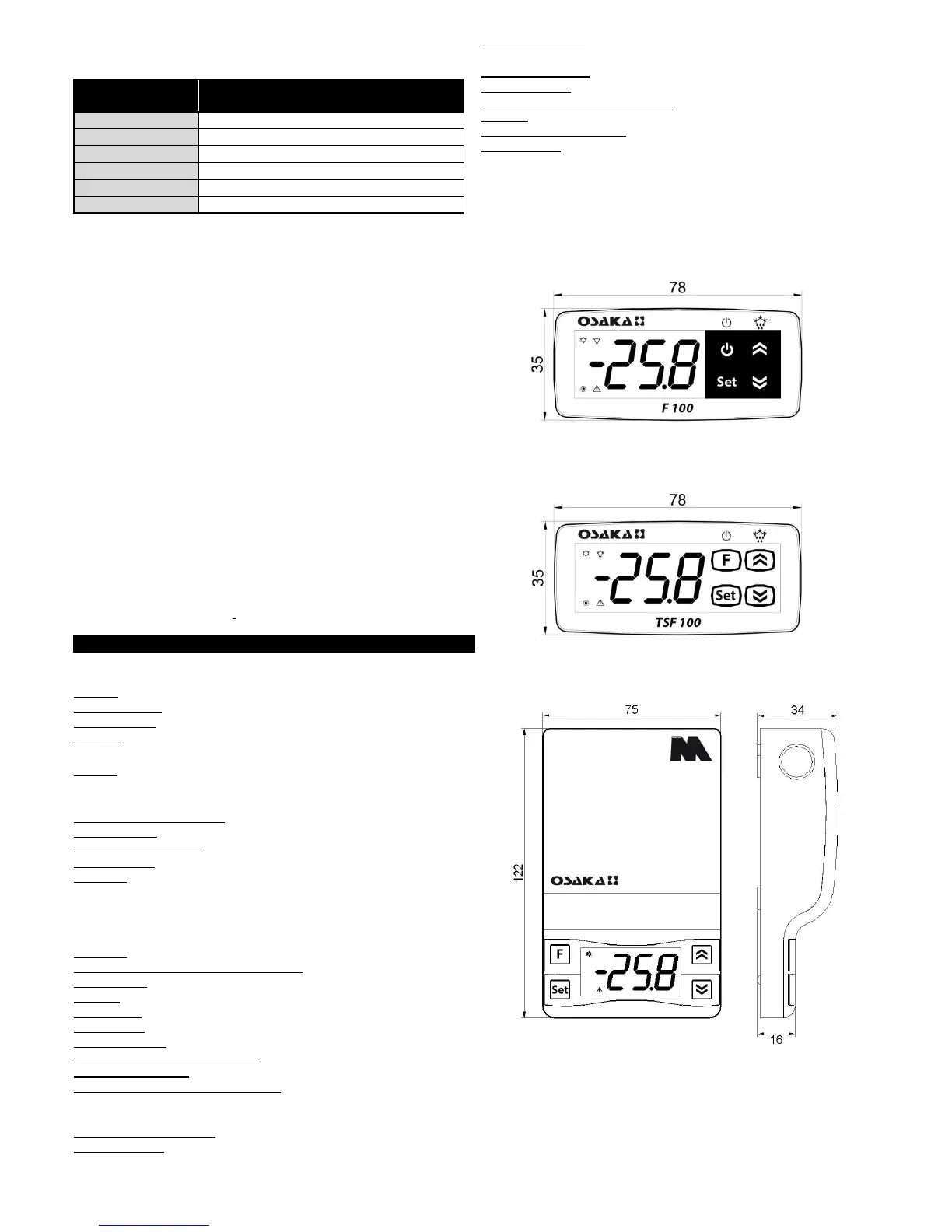
Dimensions: 78 X 35 mm, prof. 64 mm
Weight: 120 g approx.
Installation: on panel, recessed 71x29mm
Connection: Terminal block 2,5 mm2
Sealing degree: IP65
Ambient operating temperature: 0 T 50 ° C
Operating humidity: <95% RH non-condensing
Storage and transport temperature: -25 ° C T 60
7.3 - FUNCTIONAL FEATURES
Temperature regulation: ON / OFF
Defrost control: interval for compressor failure.
Measuring range: NTC: -50 ... 109 ° C / -58 ... 228 ° F; PTC: -50 ...
150 ° C / -58 ... 302 ° F
Display resolution: 1 ° or 0.1 ° (pitch -99.9 .. 99.9 ° C)
Total accuracy: + / - (0.5% FS + 1 digit)
Time measured speed (no filter): 130 ms
Display: 3 Digit 15.5 mm h
Software class structure: Class A
Compliance: Directive 2004/108/EC (EN55022 class B, EN61000-
4-2: 8KV air, 4KV cont; EN61000-4-3. 10V / m, EN61000-4-4: 2KV
power, inputs, outputs; EN61000-4-5: com 2KV power mode, 1 kV \
diff mode, EN61000-4-6:.. 3V), 2006/95/EC (EN 60730-1, EN
60730-2-7, EN 60730-2 -9)
7.4 – MECHANICAL DIMENSIONS AND MOUNTING
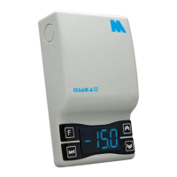
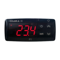
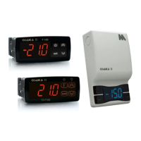
F 100
TSF 100
M 1
HOLES PANEL
- F 100/100 TSF: 29 x 71 mm
FIXING
- F 100/100 TSF: lateral Staples
- M1: Area through screw
 Loading...