OSAKA – USER MANUAL – F 500 / F 500-RS – V.1 – Page 1
If there are no alarm conditions on start-up, the time period “A.Px” is
ignored.
“A.dA” - this is the time period during which temperature alarms 1
are disabled following the end of a defrost.
Note: During defrosts, and for time period “A.dA” after defrosts,
alarm 1 is disabled, whereas during defrosts alarm 2 is always
enabled.
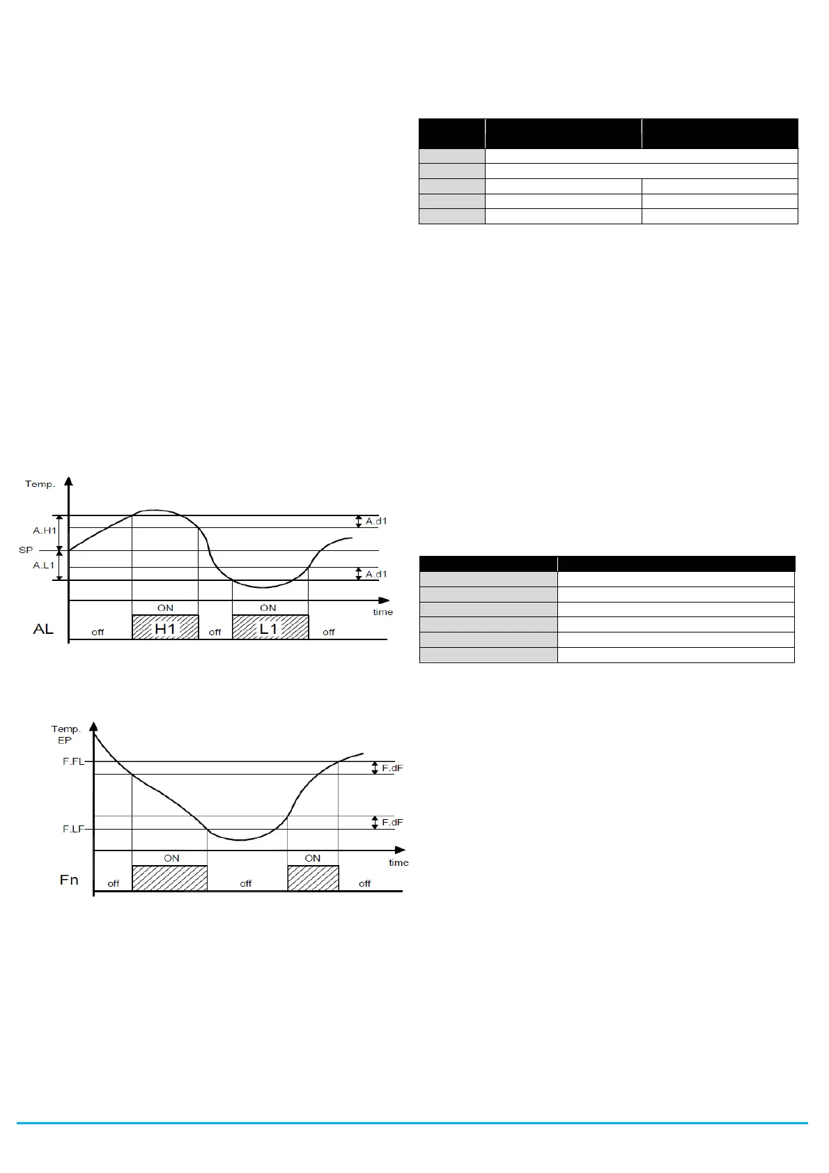
“A.t1”, “A.t2” - these are the actuation delay times for temperature
alarms 1 and 2.
Temperature alarms 1 and 2 are enabled at the end of the alarm-
disabled time periods and activated after time periods “A.t1” and
“A.t2” when the temperature measured by the probe configured for
the alarm rises above or drops below the respective maximum and
minimum alarm thresholds.
Via the parameters “A.A1” and “A.A2” it is also possible to define
at will the action of the alarms on the regulating output and on the
alarm outputs (including buzzer).
This means for example that it is possible to change the regulating
output directly, deactivating it if there are temperature alarms on the
probes configured as “Au” (e.g. “antifreeze” function) or as “cd” (e.g.
condenser “dirty” function).
If both alarms are configured with reference to the same probe, the
instrument also allows the user to control pre-alarm notifications
(e.g. notifications that do not activate the alarm output and/or the
buzzer) and alarm notifications (which do activate the alarm output
and/or the buzzer).
The alarm thresholds will be the same as those set in parameters
“A.Hx” and “A.Lx” if the alarms absolute (“A.yx” = 1, 3, 5, 7, 9, 10).
Or will be the values [”SP”+”A.Hx”] and [”SP”+”A.Lx”] if the alarms
are relative (“A.yx” = 2, 4, 6, 8).
The maxima and minima temperature alarms can be disabled by
setting the relevant parameters "A.Hx" and "A.Lx" = oF.
Triggering of the temperature alarms causes the AL alarm signal
LED to light up, activates outputs configured with an alarm function,
and activates the internal buzzer if configured.
4.10.2 - EXTERNAL ALARMS (DIGITAL INPUTS)
The instrument can notify alarms external to the instrument by
activating one or more digital inputs configured with functions
programmed as “i.xF” = 4, 5, 12, 13, 14.
Simultaneously with the configured alarm notification (buzzer and/or
output), the instrument notifies the alarm by iluminating the ALARM
led and displaying on the display the label defined for the alarm
(AL, PrA , HP, LP) alternating with the variable defined in
parameter “i.dS”.
The “i.xF”= 4 mode produces no action on the control outputs
whereas the other modes deactivate the “ot” output or deactivate all
control outputs when the digital input intervenes.
other control outputs
(“Fn”, “dF”, “Au”, “HE”).
4.10.3 - OPEN DOOR ALARM
The instrument can signal an open door alarm by activating the
digital input with the function programmed as “i.xF” = 1, 2 or 3.
When the digital input is activated the instrument show oP and after
the delay programmed in parameter “A.oA”, the instrument signals
the alarm via the activation of the configured alarm output
(buzzer/ouput).
At the intervention of the open door alarm the inhibited output will
reactivated (fans or fans + compressor).
4.11 - HACCP FUNCTION (ALARM RECORDING)
The HACCP (Hazard Analysis and Critical Control Points) function
causes the instrument to record the last 10 alarms that have
occurred together with information that is useful for determining the
criticality of the alarm.
The function is available only for instruments that have the calendar
clock.
The parameters associated with displaying HACCP alarms are
contained in the “
]
HA” group, while those associated with the
configuration are contained in the “
]
AL” group.
The following HACCP alarms can be stored in memory:
Maximum temperature alarm H1
Minimum temperature alarm L1
Maximum temperature alarm H2
Minimum temperature alarm L2
Power failure (black-out) alarm
HACCP alarms are stored provided the associated enabling
parameters are configured and the preset time configured in the
same parameter has lapsed.
It is also possible to disable alarm recording by using a suitably
configured digital input (i.xF=13) or by using the STAND-BY or
DOWN/AUX keys, suitably configured (“t.UF” or “t.Fb” = 7).
These alarms are displayed by the same display procedure as for
the programming parameters by accessing parameters “H.01” ...
“H.10” contained in the
]
HA group.
Note: see section on HACCP alarm display in chapter 2
The instrument automatically sorts these parameters from most
recent (H.01) to oldest (H.10) whenever an alarm is recorded or
deleted.
If more than 10 alarms occur, the instrument deletes the information
about the oldest alarm by overwriting it with the most recent alarm.
When this occurs the instrument increments by one the value of the
“H.dL” parameter by which it is possible to display the number of
alarms the instrument has been forced to delete when these
exceeded the permitted memory.
After selecting the parameter for the alarm which the user wishes to
display, if the label flashes this indicates that the alarm has never
been displayed (therefore not recognised).
To recognise it, simply access the parameter via the SET key and
display it.
The next time it is displayed, the parameter label will be shown solid
(not flashing).
If the alarm is still ongoing at the time of its display, the data are
displayed but the alarm is not recognised and cannot be cancelled.


 To Next Page
 Loading...