OSAKA – USER MANUAL – F 500 / F 500-RS – V.1 – Page 1
The interface circuit allows the connection of up to 32 instruments
on the same line.
To maintain the line in rest conditions a 120 Ohm resistance (Rt)
must be connected to the end of the line.
If the instrument is equipped with a serial interface, the parameter to
be programmed are the following present in the parameters group
“
]
tS” :
"t.AS" : Address of the station. Set a different number for each
station, from 1 to 255.
Note: The baud-rate are fixed at 9600 baud.
4.15 - ACCESSORIES
The instrument is equipped with a connector that allows the
connection of some accessories described as follow.
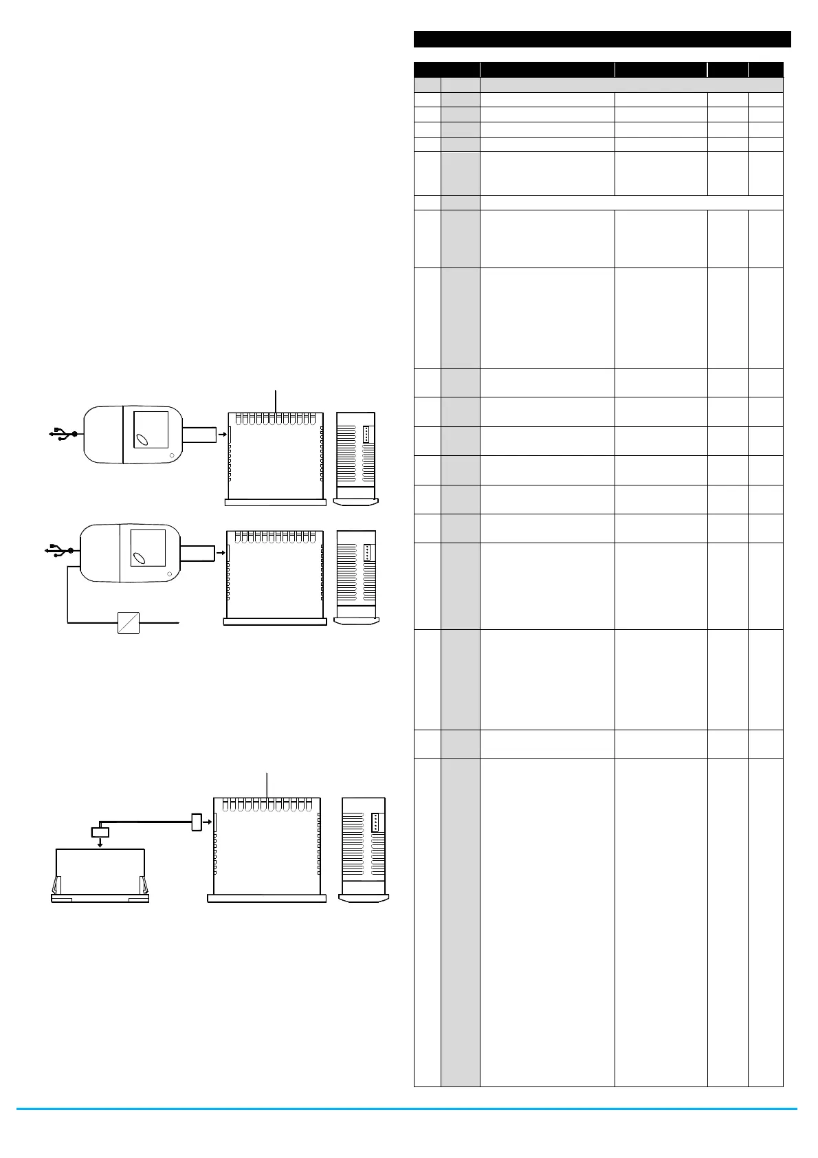
4.15.1 - PARAMETERS CONFIGURATION BY “KEY USB”
The device has a connector that allows you to transfer the operating
parameters from the "KEY USB" device equipped with a 5-pin
connector. The "KEY USB" device is used for serial programming of
devices must have the same configuration parameters, or to save a
copy of the programming device and to transfer it quickly. The
device has a USB input, allowing connection to a PC, with which,
through the software configuration "Universal Conf" or "Osaka Set
Up" is possible to configure operating parameters.
For more information, see the "KEY USB" device manual.
4.15.2 - “X2” REMOTE DISPLAY
The device is possible to connect a remote display device via a
cable X2 can be up to 10 m start. The X2 device is powered directly
from equipment, displays temperature measured by the probe Pr1
by a 2-digit display and a half.
Refer to the user manual regarding X2 device for more information.
5 - PROGRAMMABLE PARAMETERS TABLE
S. - parameters relative to Set Point
“Turbo” Set Point (or
ind. Heating Set Point
mod. HC )
i. -parameters relative to inputs
Probes Type
Pt = PTC
nt = NTC
P1 = Pt1000
Unit of measurement
and resolution (decimal
point)
C0 = °C with 1° res.
F0 = °F with 1° res.
C1 =°C with 0,1° res.
F1 = °F with 0,1° res.
Measure offset on the
display
Pr2 input function:
oF = No function
EP = Evaporator (1)
Au = Aux
cd = condenser
2E = Evaporator 2
Pr3 input function:
oF = No function
EP = Evaporator (1)
Au = Aux
cd = condenser
2E = Evaporator 2
dG = digital input
oF / EP / Au /
cd / 2E / dG
Pr3 input function:
see i.P3
oF / EP / Au /
cd / 2E / dG
Function and function
logic of digital input
di1:
0 = No function
1= Door open
2= Door open with fan
stop
3= Door open with fan
and compressor stop
4= External “AL” alarm
5= External “AL” alarm
with deactivation of
control outputs
6=Selection of active
Set Point (SP-SPE)
7= Switch on/ off
(Stand - by)
8= “Turbo" cycle
activation
9= Remote command
of AUX output
10= Disable recording
of HACCP alarms
-17 / -16/ -15 / -
14 / -13 / -12 / -
11 / -10 / -9 / -8
/ -7 / -6 / -5 / -4
/ -3 / -2 / -1 / 0 /
1 / 2 / 3 / 4 / 5 /
6 / 7 / 8 / 9 / 10
/ 11 / 12 / 13 /
14 / 15 /16 /17
S U P P LY A D A P TE R
1 2 V D C A C S U P P LY
U S B
S U P P L Y
T V R Y
ca b le 10 m M A X .
 Loading...