OSAKA – USER MANUAL – F 500 / F 500-RS – V.1 – Page 1
The instrument still cools but this selection activates automatic
switching between the three modes, Normal, Eco and Turbo, as
already described in the section on operating modes.
All time protections described in the next paragraph (P.P1, P.P2,
P.P3) always act only on the output configured as “ot”.
In the event of probe error, it is possible to set the instrument so
that that the output “ot”continues to work in cycles according to the
times programmed in the parameter “r.t1” (activation time) and
“r.t2” (deactivation time).
If an error occurs on the probe the instrument activates the output
for the time “r.t1”, then deactivates it for the time “r.t2” and so on
whilst the error remains.
Programming “r.t1” = oF the output in probe error condition will
remain switched off.
Programming instead “r.t1” to any value and “r.t2” = oF the output in
probe error condition will remain switched on.
Remember that the temperature regulation function can be
conditioned by the “Compressor Protection and output delay at
power-on”, “Defrost”, “Door open” and “external alarm with outputs
disable” functions.
4.7 - COMPRESSOR PROTECTION FUNCTION AND DELAY AT
POWER-ON
All the parameters concerning compressor protection functions are
contained in the group “
]
Pr”.
The function “Compressor Protection” aims to avoid close start ups
of the compressor controlled by the instrument in cooling
applications.
This function foresees 3 time controls on the switching on of the
output configured as “ot” associated with the temperature regulation
request.
The protection consists of preventing the output being switched on
during the times set in the parameters “P.P1”, “P.P2” and “P.P3”
and therefore that any activation occurs only after all the times has
finished.
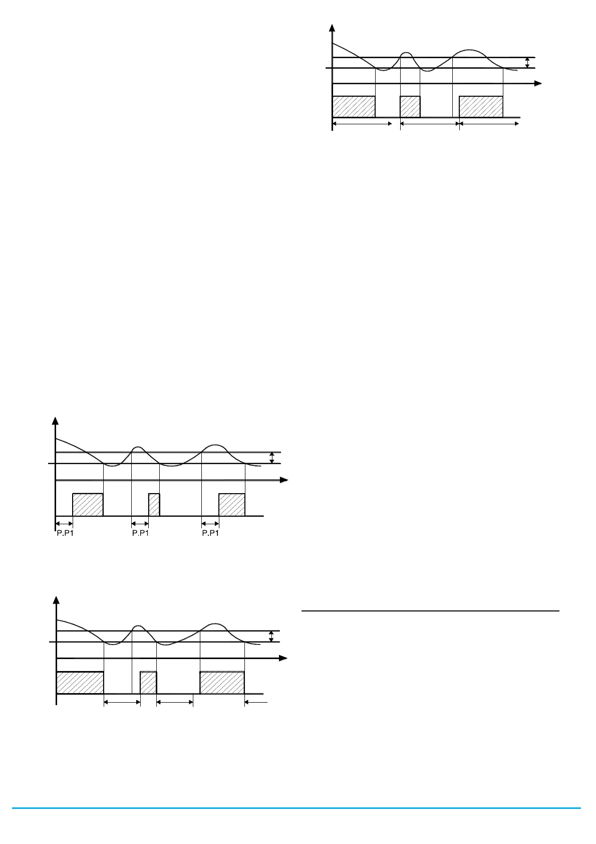
First control (par. “P.P1” ) foresees a delay to the output activation
(switching-on delay).
Second control (par. “P.P2” ) foresees an inhibition to the
activation of the output by a time delay that starts when the output
is turning off (delay after switching-off).
Third control (par. “P.P3” ) foresees an inhibition to the activation of
the output "Out" by a time delay that starts when the output was
turning on last time (delay between switching-on).
During the output inhibition the led OUT (Cool o Heat) blinking.
It is also possible to prevent activation of the output after the
instrument is turned on, for the time set in the parameter “P.od”.
During the power on delay phase, the display shows the indication
od, alternating with the normal visualisation.
All the functions are disabled by relative parameters = oF.
4.8 - DEFROST CONTROL
The defrosting control acts on the outputs configured as “ot” and
“dF”.
All the parameters concerning defrost control are contained in the
group “
]
dF”.
The type of defrosting that the instrument must carry out is set by
the parameter “d.dt” that can be programmed:
= EL - WITH ELECTRICAL HEATING (or BY STOPPING
COMPRESSOR): during defrosting, the output “ot” is deactivated
while the output “dF” is enabled.
The defrost will be by Stopping compressor if not using the “dF”
output
= in - WITH HOT GAS or INVERSION OF CYCLE:
during defrosting the outputs “ot” and “dF” are enabled
= no - WITHOUT COMPRESSOR OUTPUT CONDITIONING:
during defrosting, the output “ot” continuous to operate in order to
temperature controller while the output “dF” is enabled.
= Et - WITH ELECTRICAL HEATING AND DEFROSTING
TEMPERATURE CONTROL: during defrosting, the output “ot” is
deactivated while the output “dF” operate as evaporator
temperature control. In this mode the defrost lenght is by time-out
(time "d.dE"). During the defrost "dF" output it behaves as an
heating mode temperature control with Set = "d.tE" and fixed
differential at 1°C and operate in order to evaporator probe (EP).
4.8.1 - STARTING AUTOMATIC DEFROSTS
The automatic control of defrost occours:
- Defrosting at defined times – “Real Time Clock Defrosting”
- By interval times (regular or dynamic)
- By Evaporator temperature
- By continuous compressor running time
In order to avoid pointless defrosting the parameter “d.tS” in “d.dC”
= rt, ct, cS mode is foreseen that sets the enablement temperature
for defrosting
If the temperature measured by the probe is higher than set in the
parameter “d.tS” the defrosting is inhibited.
- Defrosting at defined times – “Real Time Clock Defrosting”
Setting the parameter “d.dC” = cL disables defrosting at intervals
(parameters “d.di” and “d.Sd”) and enables any defrosting events
programmed for defined times by means of the parameters “c.01”,
“c.02”, “c.03”, “c.04”, “c.05”, “c.06”, “c.07”, “c.08”, “c.09”,
“c.10”, “c.11”, “c.12”, “c.13” and “c.14”.
In this mode the instrument can therefore manage up to a maximum
of 14 daily defrosting events (14x7 = 98 weekly defrosts with d.8).
The events are programmable at will, including daily, using the
following settings:
d.1 = Monday ... d.7 = Sunday
d. 8 = every day
d. 9 = Mon, Tue, Wed, Thur, Fri
d.10 = Mon, Tue, Wed, Thur, Fri, Sat
d.11 = Sat and Sun
d.oF = none
T e m p.
o ff
ON
SP
tim e
r.d
o ff off o ff
ON ON
P r1
O ut
(ot)
ON
o ff
P .P 2 P .P 2 P .P 2
SP
T e m p.
tim e
r.d
ON ON
o ff o ff
P r1
O ut
(ot)
P .P 3
o ff
SP
ON
T em p .
P .P 3 P .P 3
tim e
r.d
o ff o ff
ON ON
P r1
(o t)
O ut
 Loading...