Matrix Insert Installation and Operation Manual
_______________________________________________________________________________51
APPENDIX 3: FACEPLATE INSTALLATION
NOTE: If the depth and or the opening of the masonry hearth require the use of the projection kit
AC01323 and or a faceplate backing plate kit AC01322 or AC01332, follow the instructions
included with these options before beginning the installation of the cast iron faceplate.
Remove the faceplate parts of the packaging and inspect its content. Then remove the wing nut
that secures the fan switch assembly to the floor of the convection air jacket for transport. The
faceplate installation requires a ratchet and 3/8'' box to secure each part to the front of the insert.
The back of each faceplate part is identified as follow : (A) = 24249, (B) = 24250, (F) = 24248 and
(G) = 24247.
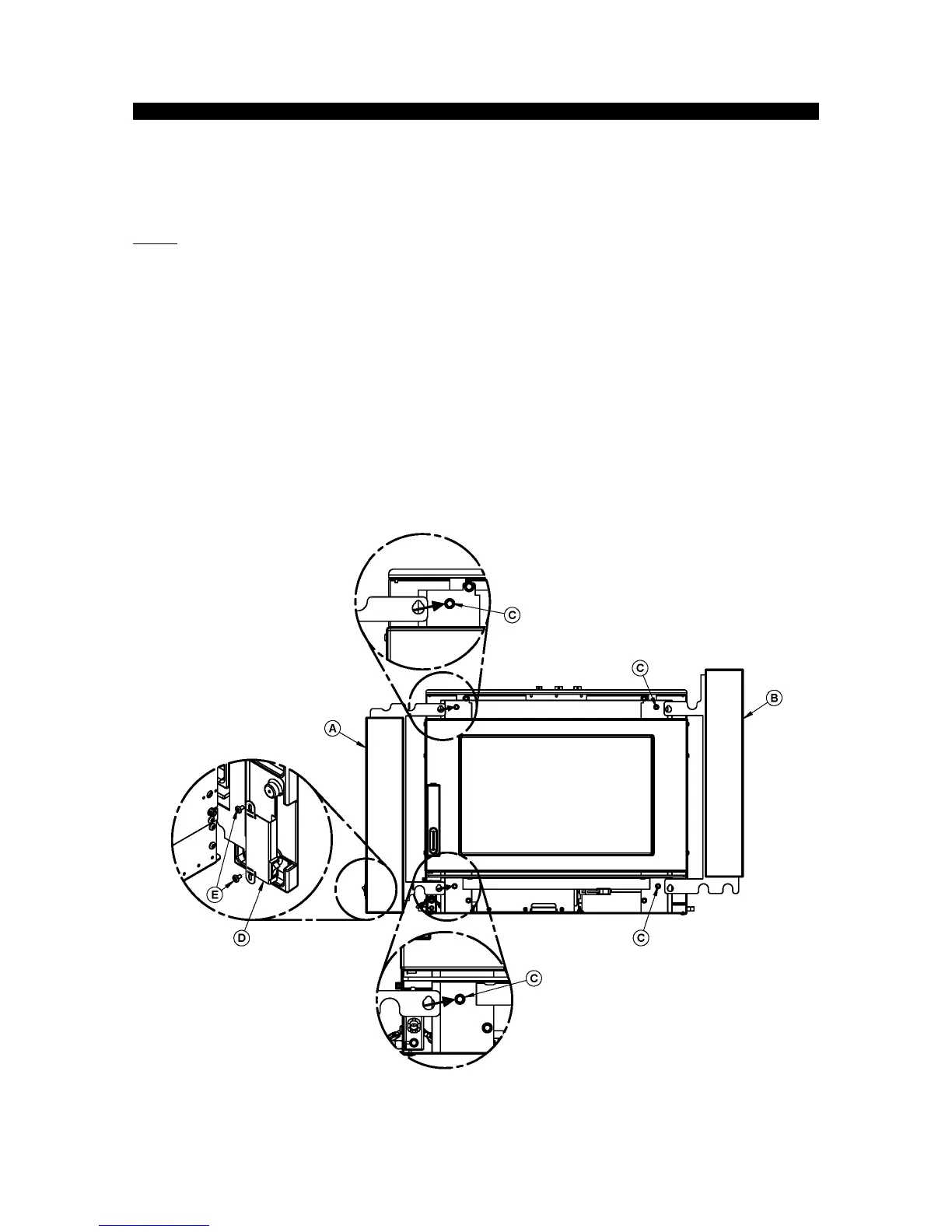
1. Secure the fan switch assembly (D) to the faceplate (A) with 2 screws (E).
2. Align the holes in the support bracket of faceplate (A) with the screws (C) already installed on
the insert, and then tighten the screws. Use the same procedure for faceplate (B).