SWG OPERATOR INSTALLATION GUIDE
- 2 -
TABLE OF CONTENTS
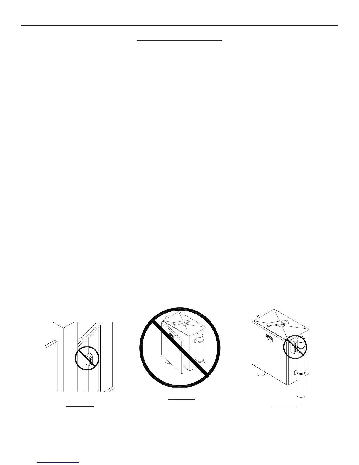
CAUTION!
DO NOT INSTALL
CONTROLS ON
THE OPERATOR
CAUTION!
ONLY QUALIFIED SERVICE
TECHNICIANS SHOULD
WORK ON AN OSCO
SWING GATE OPERATOR
CAUTION!
DO NOT INSTALL
CONTROLS ON OR
NEAR THE GATE
PRE-INSTALLATION INFORMATION
Gate Operator Classifications ......................................................................................................................................3
Safety Information and Warnings .................................................................................................................................3
Pre-Installation Information ...........................................................................................................................................3
Warranty......................................................................................................................................................................3
INSTALLATION
Wiring Specifications ...................................................................................................................................................4
Post Mounting Instructions ..........................................................................................................................................5
String Method for Nonstandard Installation of Swing Gate Operators ............................................................................6
Articulating -Style Arm Assembly Instructions .............................................................................................................7
Vent Plug Installation ...................................................................................................................................................8
Torque Limiter Adjustment ...........................................................................................................................................8
Electrical Connection and Adjustments........................................................................................................................9
Limit Cam Adjustments ...............................................................................................................................................9
CONTROL BOARD ADJUSTMENTS and ACCESSORY CONNECTIONS
Control Board Adjustments ........................................................................................................................................10
Terminal Connection Descriptions .............................................................................................................................. 11
Current Sensing Adjustments ....................................................................................................................................12
Close Direction Current Sense Adjustment ................................................................................................................12
Open Direction Current Sense Adjustment .................................................................................................................12
Maximum Run Timer Adjustment ...............................................................................................................................12
Auto Close Timer Adjustment ....................................................................................................................................12
Master/Slave Connection ...........................................................................................................................................12
Onboard L.E.D. Indicator Descriptions .......................................................................................................................13
Important Notes for Installation of Master/Slave Applications......................................................................................14
Surge Protector Instructions ......................................................................................................................................14
Control and Accessory Connection Illustrations .................................................................................................... 15-18
ILLUSTRATIONS
Loop Layout Illustration ..............................................................................................................................................19
Edge Layout Illustration #1.........................................................................................................................................20
Photo Eye Illustration.................................................................................................................................................21
TROUBLESHOOTING ...................................................................................................................................................22
PARTS LISTS
How to Order Replacement Parts...............................................................................................................................22
Model SWG Mechanical Parts Exploded View...........................................................................................................23
Model SWG Mechanical Parts List ............................................................................................................................24
Model SWG Single Phase Control Box Exploded View and Parts List .......................................................................25
Model SWG Three Phase Control Box Exploded View and Parts List ........................................................................26
Model SWG Gate Arm Assembly Parts List ..............................................................................................................27
PREVENTATIVE MAINTENANCE ..................................................................................................................................29
GATE OPERATOR INSTALLATION CHECKLIST ..........................................................................................................30