SWG OPERATOR INSTALLATION GUIDE
- 4 -
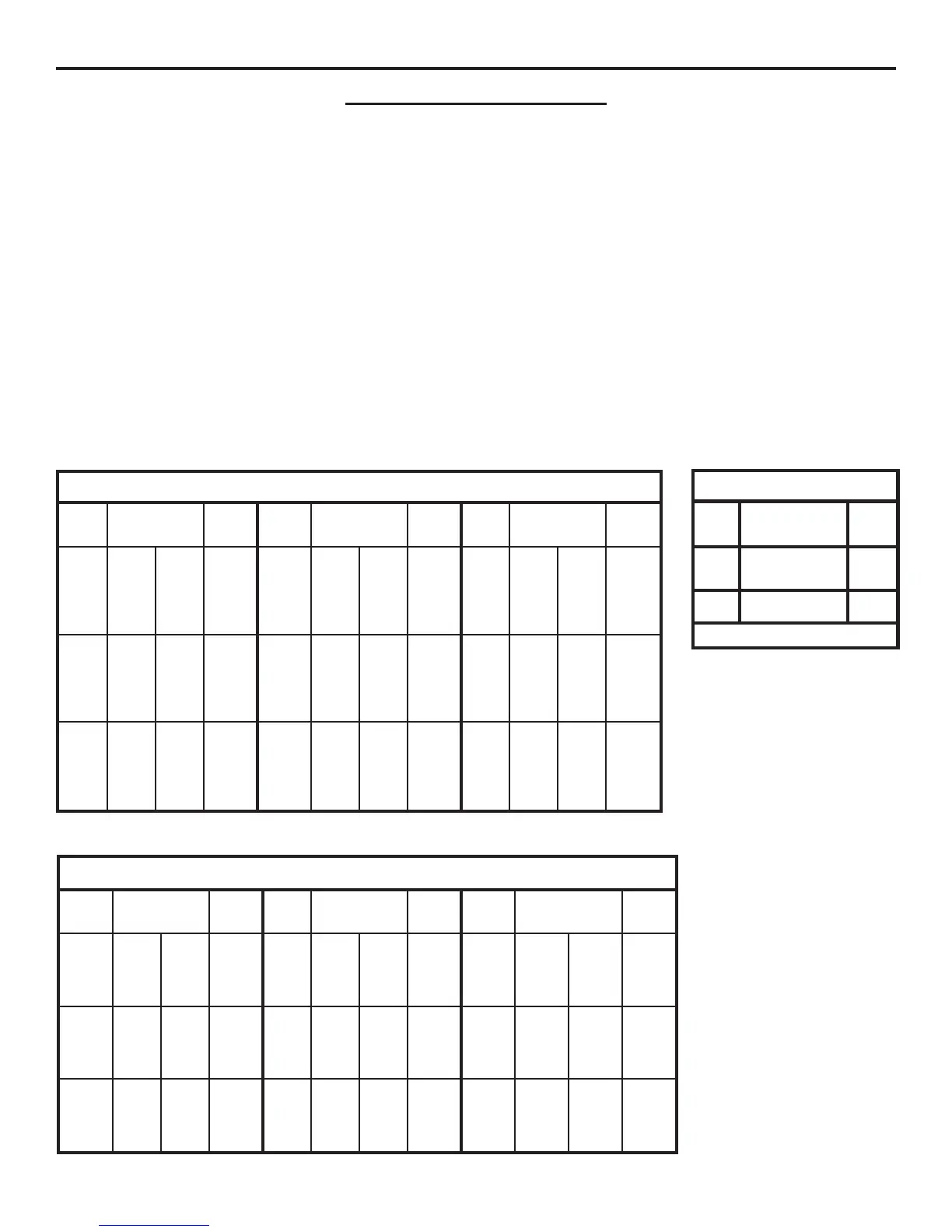
USE COPPER WIRE ONLY!
ACCESSORY WIRING
All Models
24VDC
*Over 350 ft. use DC power.
0-2000
14
24VAC
250
350*
14
12
Volts
Maximum
Distance (ft.)
Wire
Gauge
1. Select from the chart at the bottom of this page corresponding to the
model, voltage and horsepower rating of your operator.
2. The distance shown on the chart is measured in feet from the opera-
tor to the power source. DO NOT EXCEED THE MAXIMUM DIS-
TANCE. These calculations have been based on standard 115V and
230V supplies with a 10% drop allowable. If your supply is under the
standard rating, the runs listed may be longer than what your appli-
cation will handle, and you should not run wire too near the upper
end of the chart for the gauge of wire you are using.
3. When large-gauge wire is used, a separate junction box (not sup-
plied) may be needed for the operator power connection.
4. All control devices are now 24VDC, which can be run considerable
distances. 24VAC is available for other devices, such as loop detec-
tors and photo eyes.
5. Wire run calculations are based on the National Electrical Code, Ar-
ticle 430 and have been carefully determined based on motor inrush,
brake solenoids, and operator requirements.
WIRING SPECIFICATIONS
6. Connect power in accordance with local codes. The green ground
wire must be properly connected.
7. Wire insulation must be suitable to the application.
8. Control wiring must be run in a separate conduit from power wiring.
Running them together may cause interference and faulty signals in
some accessories.
9. Electrical outlets are supplied in all 115VAC models for convenience
with occasional use or low power consumption devices only. If you
choose to run dedicated equipment from these devices, it will de-
crease the distance for maximum run and the charts will no longer be
accurate.
10. A three-wire shielded conductor cable is required to connect master
and slave operators. You must use Belden 8760 Twisted Pair Shielded
Cable (or equivalent) only – OSCO part number 2500-1982, per
foot). See page 10 for details of this connection, as well as dip
switch selection. Note: The SHIELD wire should be connected
in both the master and slave operators.
MODEL SWG – SINGLE PHASE
gniriWrewoP
stloV
PH&
ecnatsiDxaM
lauDelgniS
eriW
eguaG
stloV
PH&
ecnatsiDxaM
lauDelgniS
eriW
eguaG
stloV
PH&
ecnats
iDxaM
lauDelgniS
eriW
eguaG
V511
2/1
PH
222
453
665
009
0341
111
771
382
054
517
21
01
8
6
4
V802
2/1
PH
067
0021
4291
0603
4684
083
006
269
0381
2342
21
01
8
6
4
V032
2/1
PH
498
2241
4622
0063
4275
744
117
2311
0081
2682
21
01
8
6
4
V511
4/3
PH
871
282
054
617
0411
98
14
1
522
853
075
21
01
8
6
4
802
4/3
PH
406
859
6251
4242
6583
203
874
367
2121
8291
21
01
8
6
4
V032
4/3
PH
017
8211
6971
2582
8354
553
465
89
8
6241
9622
21
01
8
6
4
V511
PH1
061
452
604
646
6201
08
721
302
323
315
21
01
8
6
4
V802
PH1
445
468
4731
4812
6743
272
234
686
2901
8371
2
1
01
8
6
4
V032
PH1
046
6101
6161
0752
0904
023
805
808
5821
5402
21
01
8
6
4
esahP3:gniriWrewoP
stloV
PH&
ecnatsiDxaM
lauDelgniS
eriW
eguaG
stloV
PH&
ecnatsiDxaM
lauDelgniS
eriW
eguaG
stloV
PH
&
ecnatsiDxaM
lauDelgniS
eriW
eguaG
V802
2/1
PH
2411
6181
0982
175
809
5441
21
01
8
V032
2/1
PH
4431
7312
0043
276
9601
0071
21
01
8
V064
2/1
PH
1483
6016
2179
1291
3503
6584
21
01
8
V802
4/3
PH
029
4641
0332
064
237
5611
21
01
8
V032
4/3
PH
4801
3271
1472
245
2
68
1731
21
01
8
V064
4/3
PH
9723
2125
1928
0461
6062
6414
21
01
8
V802
PH1
417
6311
4081
753
865
209
21
01
8
V032
PH1
048
6331
4212
02
4
866
2601
21
01
8
V064
PH1
9862
4724
8976
5431
7342
9933
21
01
8
MODEL SWG – THREE PHASE
12-02-11