SWR • SWC • SWD OPERATOR INSTALLATION GUIDE
- 2 -
TABLE OF CONTENTS
PRE-INSTALLATION INFORMATION
Gate Operator Classifications ......................................................................................................................................................... 3
Safety Information and Warnings .................................................................................................................................................... 3
Pre-Installation Information ............................................................................................................................................................. 3
Warranty ........................................................................................................................................................................................... 3
INSTALLATION
Wiring Specifications ....................................................................................................................................................................... 4
Pad Mounting Instructions ............................................................................................................................................................... 5
String Method for Nonstandard Installation of Swing Gate Operators ........................................................................................... 6
Articulating-Style Arm Assembly Instructions .................................................................................................................................. 7
Vent Plug Installation ....................................................................................................................................................................... 8
Torque Limiter Adjustment .............................................................................................................................................................. 8
Electrical Connection and Adjustments .......................................................................................................................................... 9
Limit Cam Adjustments ................................................................................................................................................................... 9
Control Box Access and Removal ................................................................................................................................................... 9
CONTROL BOARD ADJUSTMENTS and ACCESSORY CONNECTIONS
Control Board Adjustments ...........................................................................................................................................................10
Terminal Connection Descriptions ............................................................................................................................................... 11
Current Sensing Adjustments ....................................................................................................................................................... 12
Close Direction Current Sense Adjustment ................................................................................................................................. 12
Open Direction Current Sense Adjustment ..................................................................................................................................12
Maximum Run Timer Adjustment ..................................................................................................................................................12
Auto Close Timer Adjustment ....................................................................................................................................................... 12
Master/Slave Connection .............................................................................................................................................................. 12
Battery Back-Up Charger Board Configuration ............................................................................................................................. 12
Onboard L.E.D. Indicator Descriptions ......................................................................................................................................... 13
Charger Board Sleep Mode ........................................................................................................................................................... 14
Important Notes for Installation of Master/Slave Applications ...................................................................................................... 15
Surge Protector Instructions ..........................................................................................................................................................15
Control and Accessory Connection Illustrations .................................................................................................................... 16-19
ILLUSTRATIONS
Loop Layout Illustration ................................................................................................................................................................. 20
Edge Layout Illustration .................................................................................................................................................................21
Photo Eye Illustration ..................................................................................................................................................................... 22
TROUBLESHOOTING ..........................................................................................................................................................................23
PARTS LISTS
How to Order Replacement Parts ................................................................................................................................................. 23
Model SWR Mechanical Parts Exploded View .............................................................................................................................. 24
Model SWR Mechanical Parts List ................................................................................................................................................ 25
Model SWC Mechanical Parts Exploded View .............................................................................................................................. 26
Model SWC Mechanical Parts List ................................................................................................................................................ 27
Model SWR • SWC Control Box Exploded View and Parts List ..................................................................................
.................. 28
Model SWD Mechanical Parts Exploded View .............................................................................................................................. 29
Model SWD Mechanical Parts List ................................................................................................................................................ 30
Model SWD Control Box Exploded View and Parts List ................................................................................................................31
Model SWR • SWC • SWD Gate Arm Assembly Parts List ............................................................................................................ 32
Model SWD Battery Maintenance and Brush Replacement ......................................................................................................... 33
PREVENTATIVE MAINTENANCE ......................................................................................................................................................... 37
GATE OPERATOR INSTALLATION CHECKLIST .................................................................................................................................. 38
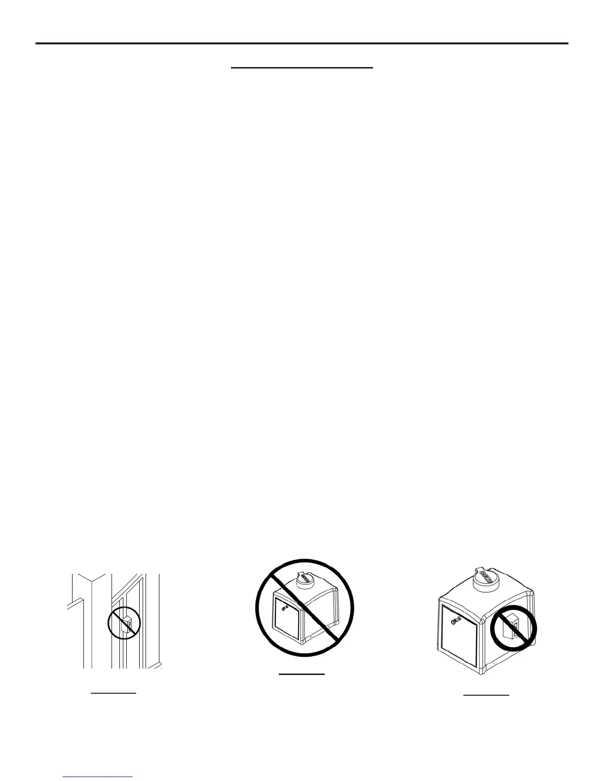
CAUTION!
DO NOT INSTALL
CONTROLS ON OR
NEAR THE GATE
CAUTION!
ONLY QUALIFIED SERVICE
TECHNICIANS SHOULD
WORK ON AN OSCO
SWING GATE OPERATOR
CAUTION!
DO NOT INSTALL
CONTROLS ON
THE OPERATOR