SWR • SWC • SWD OPERATOR INSTALLATION GUIDE
- 7 -
WELDED STYLE GATE ARM INSTALLATION INSTRUCTIONS
3-05-6
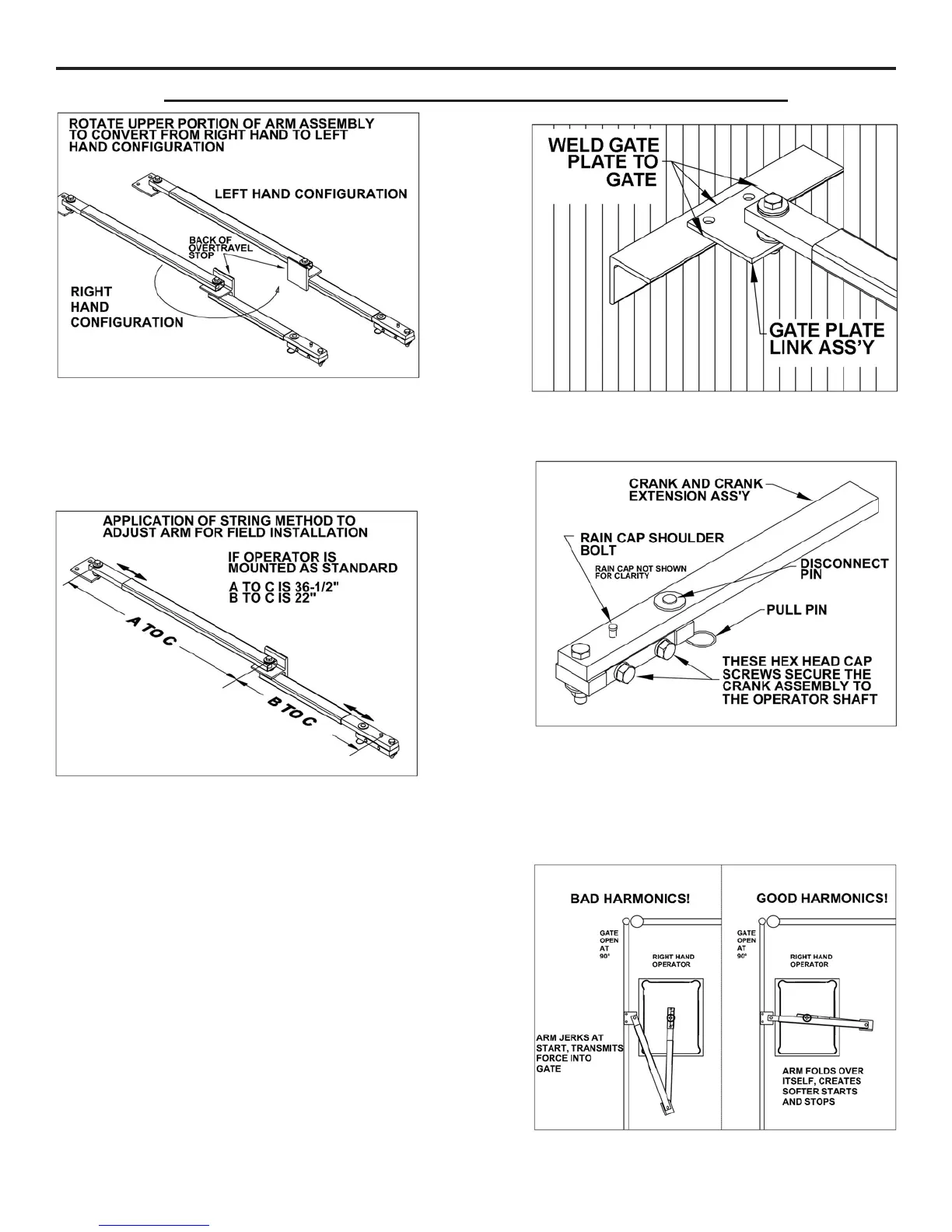
The welded style gate arm has been pre-assembled at
the factory in right-hand configuration (the back of the
overtravel stop faces toward the drive when the gate is
fully closed and the arm is installed). For a left-hand
operator, rotate the upper portion of the arm as shown
above to convert the arm into a left-hand orientation.
The gate plate supplied with the arm assembly can be
welded to the gate as shown above. Holes have been
provided for securing the gate plate to an aluminum gate.
The hex cap screws in the side of the crank assembly
are shipped loose for placement on the operator drive
shaft. Once in place, tighten these cap screws in place
by applying 75 ft•lbs of torque. If it becomes necessary
to remove the crank, you can do so by loosening these
bolts. The arm can also be disconnected for manual
operation of the gate by removing the disconnect pin.
If the operator is mounted using the standard dimen-
sions specified in the installation manual, the dimen-
sions above can be used to adjust and set the arm. If
non-standard mounting is required, utilize the string
method from the operator manual to determine the A to
C and B to C lengths required.
Once these lengths have been determined, use clamps
to temporarily attach the solid bars to their sections of
rectangular tubing. If clamps are unavailable, you may
also tack weld the parts in place. It is recommended
that you check the arm for proper action and full gate
travel before fully welding the parts together. Apply
Krylon metallic gold spray paint or equivalent to touch
up weldments when finished.
Good harmonics are necessary to minimize wear and
tear on the operator. The illustration at right shows an
example of an improperly adjusted arm and one that
has been properly installed.
 Loading...