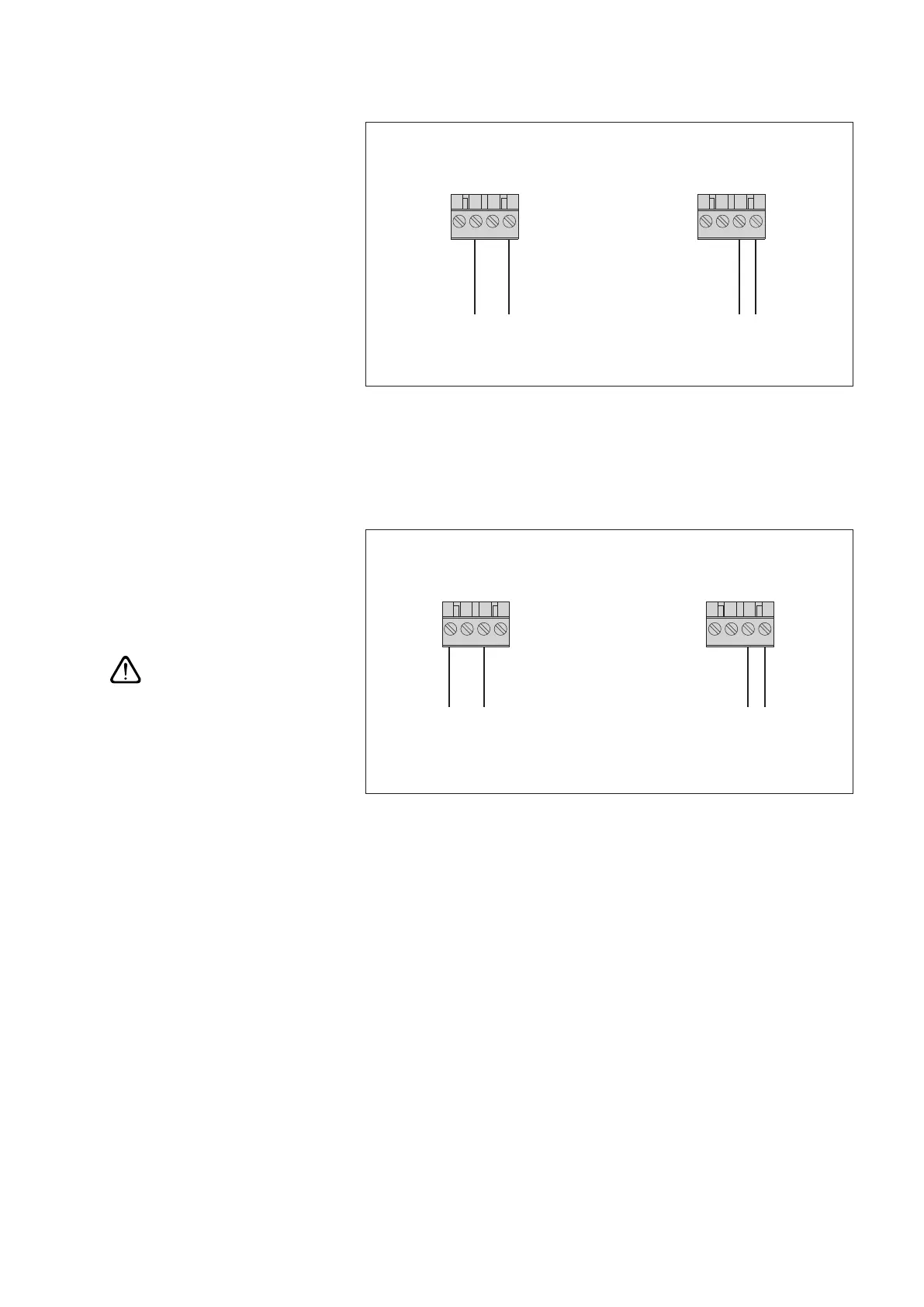
7.7 Connecting sensors having a voltage output *
7.8 Connecting sensors having a current output *
Please note: after each measurement the OTT netDL interrupts the current loop
(due to secondary effects, there is still a constant rest current of approx. 9 mA). If
other elements (e.g. display) belong to the current loop you have to close the cur-
rent loop with an external resistance (R
Burden
) and configurate the OTT net DL for a
sensor with voltage output.
* OTT netDL with expansion analog input card
(refer to Chapter 2 "Ordering numbers and version code")
Screw terminal strip
G-K
1)
/ G-M
2)
U
in
+
U
in
–
431 2
Screw terminal strip
G-K
1)
/ G-M
2)
U
in
+
U
in
–
431 2
0-50 mV / 0-1,25 V0-5 V / 0-10 V
1)
OTT netDL 500
2)
OTT netDL 1000
Fig. 14: Connecting sensors to the
OTT netDL unit that have a voltage
output (e. g. OTT ODS 4 K).
Further information can be found in the
operating instructions of the respective sensor.
Screw terminal strip
G-K
1)
/ G-M
2)
I
in
+
+24 V
I
in
–
431 2
Screw terminal strip
G-K
1)
/ G-M
2)
I
in
+
I
in
–
431 2
Version 2 : 0 (4)-20 mA
Current loop provided externally
Version 1 : 0 (4)-20 mA
Current loop provided internally
1
)
OTT netDL 500
2)
OTT netDL 1000
Fig. 15: Connecting sensors to the
OTT netDL unit that have a current
output (e. g. OTT SE 200 shaft encoder
or OTT PLS pressure probe).
Further information can be found in the
operating instructions of the respective sensor.
Please note:
– For version 1: Do not
supply the sensor externally!
– For version 2: Additionally
supply the sensor externally!
With an OTT netDL supply voltage of higher
than 24 V (28 V max.): A sensor connected
in accordance with version 1 must be
suitable for voltages higher than 24 V!
21


 To Next Page