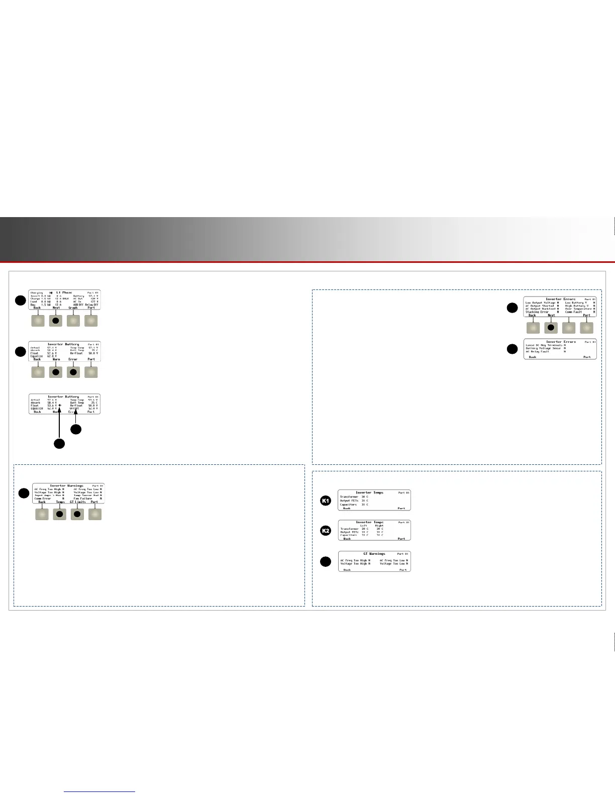
NOTES: There are several other variations on C, the <Inverter> soft key screen.
A diode symbol may be present to show “diode charging”, a low-power mode that allows fine
control of charging, selling, and load support.
o In North American Radian-class inverters, Inverter is split into L1 Phase and L2 Phase
screens (reached
using the <Next> soft key F). The screens are almost
identical, but
the
AC voltage readings are the individual L1 and L2
phases.
o From these screens, the <Next> soft key (F) brings up the Inverter Battery screen.
Screen Items (F):
Actual: The battery voltage. This reading is not compensated for temperature. See below.
Absorb and Float: The inverter’s primary charger settings for the three main charging stages.
Equalize: The inverter’s Equalization voltage setting. It is used during the equalization cycle.
Temp Comp: The battery voltage after compensation from the Remote Temperature Sensor
(RTS). If no RTS is present, Temp Comp and Actual will read the same.
Batt Temp: The battery temperature in degrees Celsius as measured by the RTS. If the RTS
is measuring on an incorrect port, ### will be displayed. See the literature for the inverter,
charge controller, or other product to determine the correct port.
Re-Float: The inverter’s Re-Float setting. It is used to return the charger from Silent mode to
the float stage.
Offset (I): The inverter’s voltage used during Offset activities, including selling.
This item is labeled Sell RE in older systems.
NOTE: If an arrow (J) appears next to Absorb, Float, or Equalize, it indicates the charger is in
that stage. The arrow will not appear if the charger is in the bulk stage or Silent mode.
o The <Error> soft key (H) displays a screen with a list of critical faults. When
an error occurs, the inverter will usually shut down.
One or more screen
items
will change from N to Y. An error is also accompanied by an even
t
message
and the red EVENTS indicator (see pages 5 and 17). See the
inverter Operator’s Manual to troubleshoot a specific error.
Screen Items (G) which may appear:
AC Freq Too High or Too Low: The AC source is above or below the acceptable frequency limit.
Voltage Too High or Too Low: The AC source is above or below the upper acceptable voltage limit.
Input Amps > Max: AC loads are drawing more current from the AC source than allowed by the input setting.
Temp Sensor Bad: An internal inverter temperature sensor may be malfunctioning. This is also indicated by an unusual
reading on the Inverter Temps screen (K). It may be called Temperature Sensor Fault.
Comm Fault: See the entry under Errors. It only appears on this screen in older models. It may be called Comm Error.
Phase Loss: A stacked inverter was ordered to transfer to an AC input source, but the source is the wrong phase or does not
appear on the input.
Fan Failure: The internal cooling fan is not operating properly. Lack of cooling may derate the inverter’s output wattage.
o The <Temps> soft key (K) displays the Inverter Temps screen.
The internal temperature sensor readings are shown in degrees Celsius.
The sensors
are located on the main transformer, the heat sink for
the
Field Effect
Transistors (FETs), and the filter capacitors.
Normally all
three
read approximately the same. An unusual reading can
indicate a
defective sensor.
o K1 shows these three readings for FX-class and FXR-class inverters.
K2 shows a
total of six readings for Radian-class inverters.
Radian
inverters have twin (right and
left) power modules. Each module
has
indepen
dent sensors and three separate readings.
o The <GT> soft key (L) displays the GT Warnings screen. It shows
reasons
why the inverter might stop selling power. If any reasons
are
valid
, one or more items will change from N to Y. It is only
available in
Radian-class and FXR-class inverters in Grid Ti
ed input mode.
It is not
visible in
FX-class inverters. The screen may be called IEEE Warnings
.
o The <Warn> soft key (G) displays a series of screens with a list of non-critical
faults and other information. When an inverter suffers a warning, one or mo
re
items in G will
change from N to Y
.
A
warning is also accompanied by an event message and the red EVENTS
indicator (see pages 5 and 17). Some warnings can become errors if left
un
attended. Frequency and voltage warnings are meant to warn of
a
proble
matic AC source. See the inverter Operator’s Manual for
more information
on
troubleshooting a specific warning.
Screen Items (H) which may appear:
Low Output Voltage: Inverter AC regulation cannot be maintained under high load.
AC Output Shorted: Inverter maximum surge current was exceeded due to severe overload.
AC Output Backfeed: Another AC power source (out of phase with the inverter) was
connected to the AC output.
Stacking Error: A programming problem among stacked units. (This often occurs if no master was assigned.)
Low Battery V: DC voltage is below the Low Battery Cut-Out (LBCO) point. (See the MATE3s Programming Guide.)
High Battery V: DC voltage is above the inverter’s maximum allowed level.
Over Temperature: Maximum operating temperature was exceeded.
Comm Fault: Inverter suffered an internal communication failure and may need service.
Phase Loss: See the entry under Warnings. It only appears on this screen in older models.
NOTE: The
<Next> soft key (M) appears in FXR and Radian (A and E model) inverters with additional items.
Screen Items (M) which may appear:
Loose DC Neg Terminals: Loose DC connection on internal power module. May read Loose DC Neg Terminals (L) or (R).
Battery Voltage Sense: Internal sensing has detected voltages that are grossly outside the normal range.
AC Relay Fault: AC transfer relay damaged.
Inverter Soft Key (continued)
Warnings
Errors
Temperatures
C
F
G
H
L
F
G H
J
I
L
K
NOTE: The GT Warnings have the same names as the Disconnect messages shown on page 18, but they are not the same.
GT Warnings have to do specifically with selling (or not selling) power, while the Disconnect messages are general reasons for
disconnecting from any source.
M
M
Bullet styles (from PRG):
 Loading...