Multidis SF
Technical description
3. Technical description
3.1 Design
4
5
1
2 3
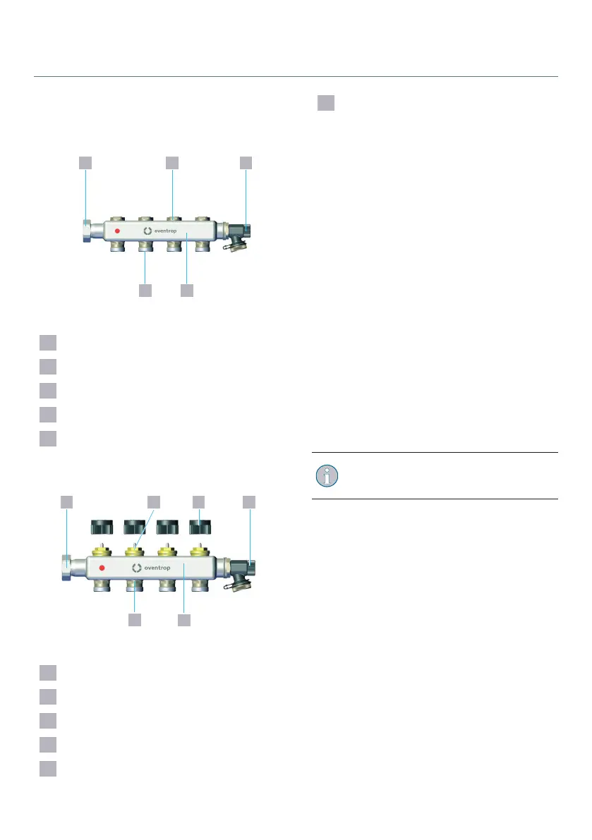
Fig. 1: Design of the flow distributor
1 Union nut
2 Regulating insert
3 Fill and drain cock G¾
4 Flow distributor
5 Connection nipple with G ¾ external
thread (Eurocone according to DIN EN
16313)
1
2
3 4
5
6
Fig. 2: Design of the return collector
1 Union nut
2 Valve insert
3 Protection cap
4 Fill and drain cock G¾
5 Return collector
6 Connection nipple with G¾ external
thread (Eurocone according to DIN EN
16313)
3.2 Functional description
The Multidis SF heating circuit distributor/
collector serves the distribution of the
medium to the corresponding surface heating/
cooling circuits.
The valve inserts in the return collector have a
M30 x 1.5 connection thread. The valve inserts
can be equipped with a thermostatic head or
actuator for individual room temperature
control.
Printed stickers are included with the heating
circuit distributor/collector to identify the
individual circuits. You can attach these to the
heating circuit distributor/collector.
The heating/cooling circuits can be filled,
flushed and bled via the fill and drain cocks.
Install a ball valve in front of the flow
distributor/return collector for the
isolation of the supply and return pipe.
19140655281-V01.07.2021



 To Next Page