EasyManua.ls Logo

oventrop HydroControl M - User Manual

oventrop HydroControl M
209 pages
Print Icon
To Next Page IconTo Next Page
Loading...
HydroControl M
Betriebsanleitung
DE
Änderungen vorbehalten Alle Rechte vorbehalten DE-03123-10658-DB-V2328 1
Datenblatt
HydroControl M
Strangregulierventil
mit Messblende
PN 25
DN 15…50
Strangregulierventil für den statischen hydraulischen Abgleich von Rohrnetzen in geschlossenen Heizungs- und Kühlwasseran-
lagen. Es bietet eine Messfunktion über eine feste Messblende was gleichzeitiges Messen und Einstellen ermöglicht.
Das HydroControl M besteht aus einem durchflussoptimierten Schrägsitzgehäuse, einem Ventileinsatz mit doppelter O-Ring
Abdichtung, ergonomisch gestaltetem Handrad, geringer Steigung und ausgefeiltem Kegel, der Messblende sowie zwei Hydro-
Port Hilfsventilen. Alle Bedienelemente sind stirnseitig angeordnet.
Funktionen
Durchflussregulierung mit reproduzierbarer, blockierbarer und plombierbarer Voreinstellung
Absperrung
Anschluss zur Durchflussmessung
Anschluss für Impulsleitung
Entleeren, Füllen und Entlüften des Anlagenteils vor oder hinter dem Ventil
Merkmale
+ Feste Messblende ermöglicht gleichzeitiges Messen und Einstellen
+ Alle Funktionen für einfache Auswahl immer enthalten
+ Neue HydroPort Hilfsventile zum einfachen, schnellen und sicheren Anschluss von Zubehör
vod k obsluze
CZ
Operating instructions
EN
Instrucciones de uso
ES
Notice d‘utilisation
FR
Üzemeltetési útmuta
HU
Istruzioni per l‘uso
IT
Bedieningsinstructies
NL
Instrukcja eksploatacji
PL
  
RU
Bruksanvisning
SV
vod na prevádzku
SK
操作指南
ZH
1000086521_10242266 000 00

Table of Contents

Question and Answer IconNeed help?

Do you have a question about the oventrop HydroControl M and is the answer not in the manual?

Overview

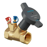
The Oventrop HydroControl M is a double regulating valve designed for static hydraulic balancing in closed-loop heating and cooling systems. It features a fixed orifice metering station, enabling simultaneous measurement and adjustment of flow rates. This valve is suitable for installation in both supply and return pipelines and can function as a partner valve for a differential pressure control valve.

Function Description

The HydroControl M facilitates hydraulic balancing of individual pipelines through a presetting mechanism on its handwheel. The flow rate is regulated by limiting the valve plug's stroke, thereby adjusting the opening between the plug and the valve seat. The low thread pitch of the valve allows for very precise adjustments. The valve's position is indicated on the front of the handwheel via a scale ranging from 0.0 (closed) to 4.85 (fully open), with increments of 0.05.

A key feature is the integrated fixed orifice metering station, which, in conjunction with the HydroPort auxiliary valves, allows for real-time flow measurement and adjustment. This means the valve can be set precisely based on the flow value displayed on a connected measuring device.

Important Technical Specifications

The HydroControl M is available in various nominal sizes, from DN 15 to DN 50, each with specific Kv values and measurement Kv values.

  • Nominal Sizes and Kv Values:

    • DN 15 ULF: Kvs value 0.19, Measurement Kv value 0.29
    • DN 15 LF: Kvs value 0.4, Measurement Kv value 0.62
    • DN 15 MF: Kvs value 0.9, Measurement Kv value 1.28
    • DN 15: Kvs value 2.2, Measurement Kv value 2.74
    • DN 20: Kvs value 4.3, Measurement Kv value 5.51
    • DN 25: Kvs value 8.6, Measurement Kv value 10.7
    • DN 32: Kvs value 15.9, Measurement Kv value 22.8
    • DN 40: Kvs value 23.4, Measurement Kv value 35.6
    • DN 50: Kvs value 35.0, Measurement Kv value 54.8
  • Operating Conditions:

    • Max. operating temperature (ts): 150°C
    • Min. operating temperature (ts): -20°C
    • Max. operating pressure (ps): 25 bar (PN 25)
    • Medium: Heating and cooling water according to VDI 2035 or ÖNORM 5195; water-glycol mixtures with max. 50% glycol content. For glycol mixtures, correction factors related to the specified chart values must be considered.
  • Materials:

    • Body: Dezincification resistant brass
    • Seal: EPDM, PTFE
    • Handwheel: Plastic
  • Dimensions (for internal thread version):

    • All nominal sizes (DN 15 to DN 50) have a 'B' dimension of 109 mm.
    • 'L1' dimensions range from 76 mm (DN 15) to 159 mm (DN 50).
    • 'L2' dimensions range from 147 mm (DN 15) to 199 mm (DN 50).
    • 'H' dimensions range from 131 mm (DN 15) to 184 mm (DN 50).
    • Weight ranges from 0.6 kg (DN 15) to 3.1 kg (DN 50).

Usage Features

The HydroControl M is designed for ease of use and precise control.

  • Presetting and Locking: The presetting on the handwheel can be locked using an internal clip, preventing unauthorized adjustments. It can also be lead-sealable for tamper-proofing.
  • HydroPort Auxiliary Valves: Each valve is equipped with two HydroPort auxiliary valves. These valves allow for easy and secure connection of accessories via a snap lock. They open with a short turn (a quarter turn with a 14 mm spanner for pressure pickup, or fully open for filling and draining).
  • Flow Measurement: An Oventrop OV-DMC 3 measuring device can be connected directly to the HydroPort valves using measuring hoses. The OV-DMC 3 calculates and displays the flow rate in real-time based on the measured differential pressure and the valve's Kv value. If two temperature sensors are used, the power output is also calculated and displayed.
  • Automatic Valve Identification: The OV-DMC 3 system stores Kv values for all Oventrop control valves and other common control valves. It can automatically identify the valve model, nominal size, and presetting using a smartphone camera, simplifying and speeding up the process of determining the correct Kv value. This function is specific to Oventrop double regulating valves.
  • Installation Flexibility: The valve can be installed in any position. For maintenance, it is recommended to install shutoff valves upstream and downstream of the valve or system section.
  • Impulse Tube Connection: When used as a partner valve with a differential pressure control valve (e.g., HydroControl D), an impulse tube connects the two valves. The connection is secured with a fastening screw and a sealing cap.

Maintenance Features

  • Accessibility: Ensure the valve remains easily accessible after installation for any future maintenance or adjustments.
  • Contamination Prevention: Before installation, ensure the product and pipework are free from contamination. If the operating medium is contaminated, a strainer should be installed in the supply pipe.
  • Lubricant Warning: Do not use greases or oils during mounting, as they can damage the seals. If necessary, flush dirt particles and grease/oil residues from the pipework.
  • Depressurisation for Work: All installation and maintenance work on the heating or cooling circuit must only be carried out when the system is depressurised to prevent injury from pressurized media.
  • Temperature Considerations: When working on hot or cold components, wear appropriate protective clothing and, if necessary, wait until the component has reached approximately ambient temperature.
  • Dismantling and Disposal: At the end of its service life or in case of irreparable defect, the product must be dismantled and disposed of in an environmentally friendly manner, or its components recycled according to local regulations. Packaging materials should also be disposed of responsibly.

oventrop HydroControl M Specifications

General IconGeneral
Brandoventrop
ModelHydroControl M
CategoryPlumbing Product
LanguageEnglish

Related product manuals