. INSTALLATION
14
D r
L\
,..-
.,
o
7/18
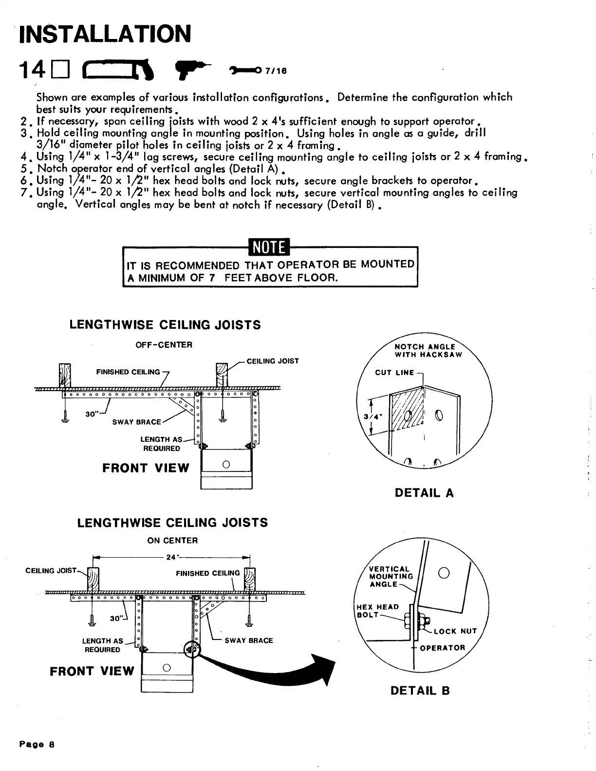
Shown are examples
of
various installation configurations. Determine the configuration which
best suits your requirements.
2.
If
necessary, span
ceiling
·,oists with wood 2 x 4's sufficient enough to support
operator.
3.
Hold ceiling mounting ang e in mounting position. Using holes in angle
as
a guide, drill
3/16
11
diameter pilot holes in
ceiling
joists or 2 x 4 framing.
4.
Using
1/4
11
x
1-3/4
11
lag screws, secure ceiling mounting
angle
to
ceiling
joists or 2 x 4 framing.
5.
Notch operator end of
vertical
angles (Detail
A)
•
6.
Using
1/4
11
- 20 x
l/.2
11
hex head bolts and lock nuts, secure angle brackets to
operator.
7.
Using
1/4
11
- 20 x
l/.2
11
hex head bolts and lock nuts, secure vertical mounting angles to
ceiling
angle. Vertical angles may
be
bent
at
notch if necessary (Detail B).
IT IS RECOMMENDED THAT OPERA TOR
BE
MOUNTED
A MINIMUM OF 7 FEET ABOVE FLOOR.
LENGTHWISE CEILING
JOISTS
CEILING JOIST
OFF-CENTER
FINISHED CEILING
30"
SWAY BRACE
LENGTH AS
REQUIRED
0
FRONT
VIEW
0
CEILING JOIST
LENGTHWISE CEILING
JOISTS
ON
CENTER
-------
24"-------1-.
FINISHED CEILING
SWAY BRACE
FRONT
VIEW
O
Page
8
NOTCH
ANGLE
WITH
HACKSAW
DETAIL A
OPERATOR
DETAIL
B





 To Next Page