This document serves as a quick guide for the OWON HDS200 Dual Channel Series of handheld oscilloscopes, covering models HDS272(S), HDS242(S), HDS2102(S), and HDS2202(S). It provides essential information on safety, general inspection, oscilloscope operation, multimeter usage, waveform generator (optional) functionality, troubleshooting, and maintenance.
Function Description
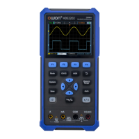
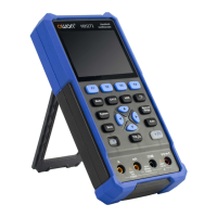
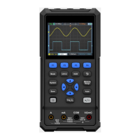
The OWON HDS200 series devices are handheld oscilloscopes designed for dual-channel measurements. They integrate multiple functions, including an oscilloscope, a multimeter, and an optional waveform generator, making them versatile tools for various electrical testing and measurement tasks.
As an oscilloscope, the device allows users to visualize and analyze electrical signals over time. It features two input channels (CH1 and CH2) for simultaneous signal acquisition. The display area shows the waveform, along with critical information such as trigger status, time base, trigger horizontal position, trigger position within storage depth, trigger horizontal displacement, and the current waveform window position in memory. It also indicates battery power, external power supply status, and USB disk connection. The oscilloscope supports various coupling modes (DC, AC, Ground) and offers automatic setting for quick waveform display.
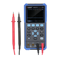
The integrated multimeter function enables precise measurements of various electrical parameters. It supports DC voltage, AC voltage, DC current, AC current, resistance, diode testing, continuity testing, and capacitance measurement. The multimeter interface displays the measurement type, range (manual or auto), current measurement range, battery power, and the measured value with its unit. It also allows for switching between resistance, buzzer, diode, and capacitance functions, and offers relative value measurement for DC current, DC voltage, and resistance.
For models equipped with the optional waveform generator, the device can output four basic waveforms (sine wave, square wave, ramp wave, pulse wave) and eight arbitrary waveforms. This feature is useful for testing circuits by providing controlled input signals.
Usage Features
Oscilloscope Operation:
- Front Panel and Keys: The device features a front panel with multi-function keys (F1-F4), a return key, measurement menu key, zoom/move keys, automatic setting key, stop/run key, trigger menu key, and a power switch key. Dedicated keys are provided for saving settings, system settings, and switching between oscilloscope and multimeter modes, as well as channel selection (CH1/CH2).
- Input Connectors: CH1 and CH2 input connectors are used for oscilloscope probes.
- Horizontal Time Base: The HOR key allows adjustment of the horizontal time base and observation of corresponding state information changes. Direction keys enable horizontal displacement of the signal.
- Waveform Navigation: Direction keys are used for vertical and horizontal movements of waveforms, time base changes, voltage cursor movements, and trigger level adjustments.
- Automatic Setting: The "Auto" key quickly sets up the oscilloscope for displaying a stable waveform, such as a 1kHz/3.3Vpp square wave from the probe compensator.
- Probe Compensation: Before initial use, probes must be compensated to match the input channel, preventing measurement errors. This involves connecting the probe to the compensator, setting the attenuation coefficient, and adjusting the probe until the displayed square wave is correct.
- Probe Attenuation Coefficient Setting: Users can set the probe attenuation coefficient (e.g., 10X) in the oscilloscope menu and on the physical probe switch to ensure accurate vertical position factor. It's crucial that the probe switch setting matches the menu setting.
- Safe Use of Probe: Probes are designed with a safety ring to protect fingers from electric shocks. Users are advised to keep fingers behind this ring and avoid touching metal parts of the probe head when connected to a voltage source. Always connect the probe to the instrument and ground terminal before measurements.
Multimeter Operation:
- Input Ends: The multimeter uses four 4-mm safety banana plug input ends: A, mA, COM, and VΩC.
- Measurement Selection: The device allows selection of AC or DC voltage and current measurements.
- Range Adjustment: Users can switch between manual and automatic ranging for measurements.
- Hold Function: The "Hold" function allows users to freeze the current reading on the display.
- Output Connection: The waveform generator output is available via a BNC cable connected to the "GEN Out" port.
- Waveform Selection: The "Mode" button switches to the waveform generator interface, where F1 selects the desired waveform type.
- Parameter Setting: Parameters for the selected waveform can be adjusted using F2-F4 and the direction keys.
- Output Control: The "Run/Stop" key controls the signal output (ON/OFF).
Maintenance Features
General Maintenance:
- Cleaning: The instrument and probes should be cleaned frequently. Use a soft cloth to wipe off dust from the exterior. For the LCD screen, be careful not to scratch the transparent protection screen. A damp, non-dripping soft cloth with mild detergent or water can be used for cleaning, but ensure the power supply is disconnected. Avoid abrasive chemical cleaning agents.
- Moisture Prevention: Ensure the instrument is completely dry before re-energizing to prevent electrical short circuits or personal injury.
- Storage: Do not store the instrument in direct sunlight for extended periods. Avoid contact with spray, liquid, or solvents to prevent damage.
Battery Charging and Replacement:
- Charging: If the device cannot be turned on after long-term storage, it may be due to a depleted battery. Pre-charge the device with the adapter for 0.5 to 1 hour before attempting to turn it on. Regular charging is recommended during long storage periods to prevent over-discharge.
- Charging Method: The battery can be charged via the power adapter using the USB data cable or by connecting the oscilloscope to a computer/other equipment via a USB data cable.
- Charging Time: Charging times vary by model: ≥4.5 hours for models <100MHz and ≥4 hours for models ≥100MHz.
- Battery Indicators: The screen displays symbols for power-on charging status, battery power supply, and a low battery warning (approximately five minutes of use time left).
- Temperature: To prevent battery overheating, ensure the ambient temperature during charging does not exceed specified limits.
- Battery Replacement: Battery replacement should only be performed by qualified personnel using lithium batteries of the same specification.
Troubleshooting:
The guide includes a troubleshooting section to address common issues such as:
- Device not turning on: Suggests charging the battery for 15 minutes before attempting to power on.
- Device turning off after startup: Indicates a depleted battery.
- Multimeter displaying 'E': Suggests selecting the measurement type or restarting the oscilloscope.
- Incorrect voltage amplitude in oscilloscope mode: Advises checking consistency between channel attenuation coefficient and probe error ratio.
- Unstable waveform display: Recommends checking trigger source and ensuring trigger electrical level is within waveform range.
- Nothing displayed after pressing RUN/STOP: Suggests checking trigger mode and electrical level, or using the "Auto" function.
- Slow display speed: Notes that this is normal when average value sampling or longer display durations are set.