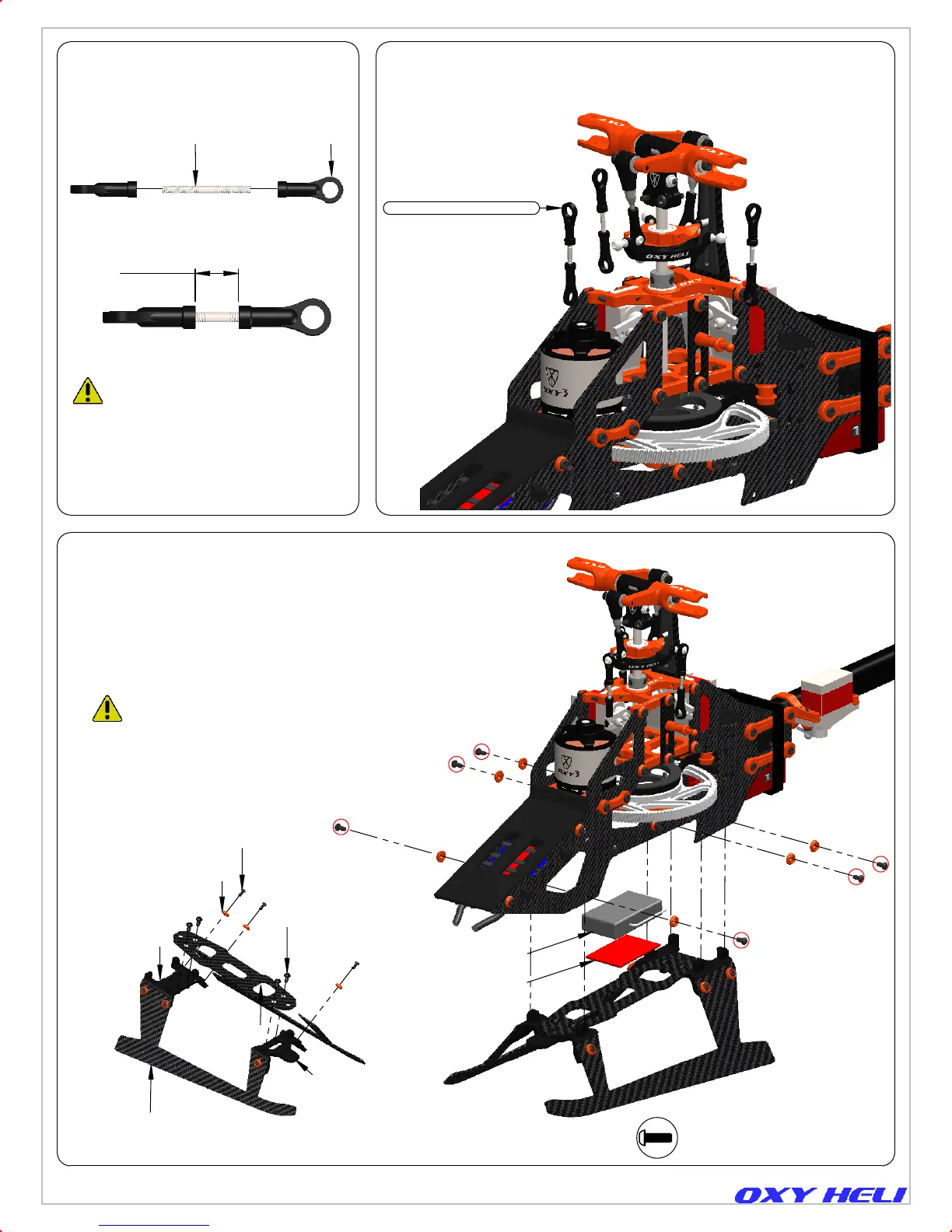
Ref 7 mm
It is really important the servo rods screw onto
the linkages the same amount. The Plastic
ball links have a oxy logo to give you
information about turn adjustment, but have
a symmetrical ball socket shape and can be
installed in either direction to achieve the
best fine tuning.
OXY0010
M1.6x14 Thread Rod
2 x OXY0011
4mm-Linkage Ball
3 x Servo Rod Assembly
Sattelite
Use Double - Side
Tape to hold Satelite
DR1683
Landing Gear Skid
6 x TBEM2x4
M2X4 Buttom Screw
6 x DR0268
Frame C washer
4 x TBEM2.5x5
M2.5X5 Buttom
Screw
DR1682
Back Landing
Gear Support
DR1681
Front Landing
Gear Support
OXY0031
Bottom Plate
Servo Rod Assembled.
(Box 02 / Bag 10)
Install Sevo rod into Swash Plate and Servo.
Page 32
Once the servo connectors are in place and
secured with cable ties, you can finalize
the assembly by installing the landing gear.
Landing Gear Assembly.
(Box 02 / Bag 11)
6 x TBEM2X4 BUTTON SCREW M2X4
Chapter 18, Servo Rod and Landing Gear Installation
Instruction Manual Rev 1
 Loading...