ONLINE MANUAL
Scan this QR Code with your
mobile device to take you to
the online manual.
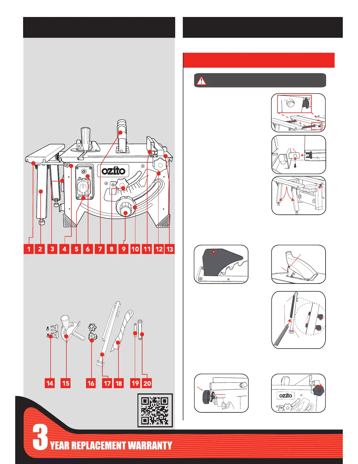
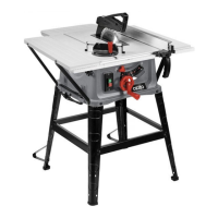
1. Integrated Extension Table
2. Folding Legs
3. Push Stick Holder
4. Ext. Table Lock Knob
5. On/Off Safety Switch
6. Overload Protection Reset
7. Blade Guard
8. Bevel Lock Knob
9. Blade Depth Adjustment Knob
10. Bevel Adjustment Handwheel
11. Rip Fence Extrusion
12. Rip Fence Lock Knob
13. Rip Fence Extrusion Locks
TABLE SAW
KNOW YOUR PRODUCT
1. ASSEMBLY
2. Place the rip fence on the table top, either the left or right hand
side of the blade.
3. Now screw the rip fence lock knob through the fence and into
the metal plate on each end.
1. Mount blade guard on the riving knife so that the bolt ts through
the hole in the riving knife.
SETUP & PREPARATION
Blade Guard
Rip Fence
3. Unfold legs. Once the extension
table is at desired distance, use the
extension table lock knobs (front &
rear) to lock table into position.
WARNING!: ENSURE THE TOOL IS DISCONNECTED
FROM THE POWER SUPPLY BEFORE ASSEMBLY
1. The extension table rods must
align with the holes in the table as
well as the plastic eyelets. These
eyelets are controlled by the
small adjustable knobs located
underneath the table and may
need to be rotated to align with
rods
2. After tting extension table lift up
and t the supplied caps into the
end of the rods, screw into place
Integrated Extension Table