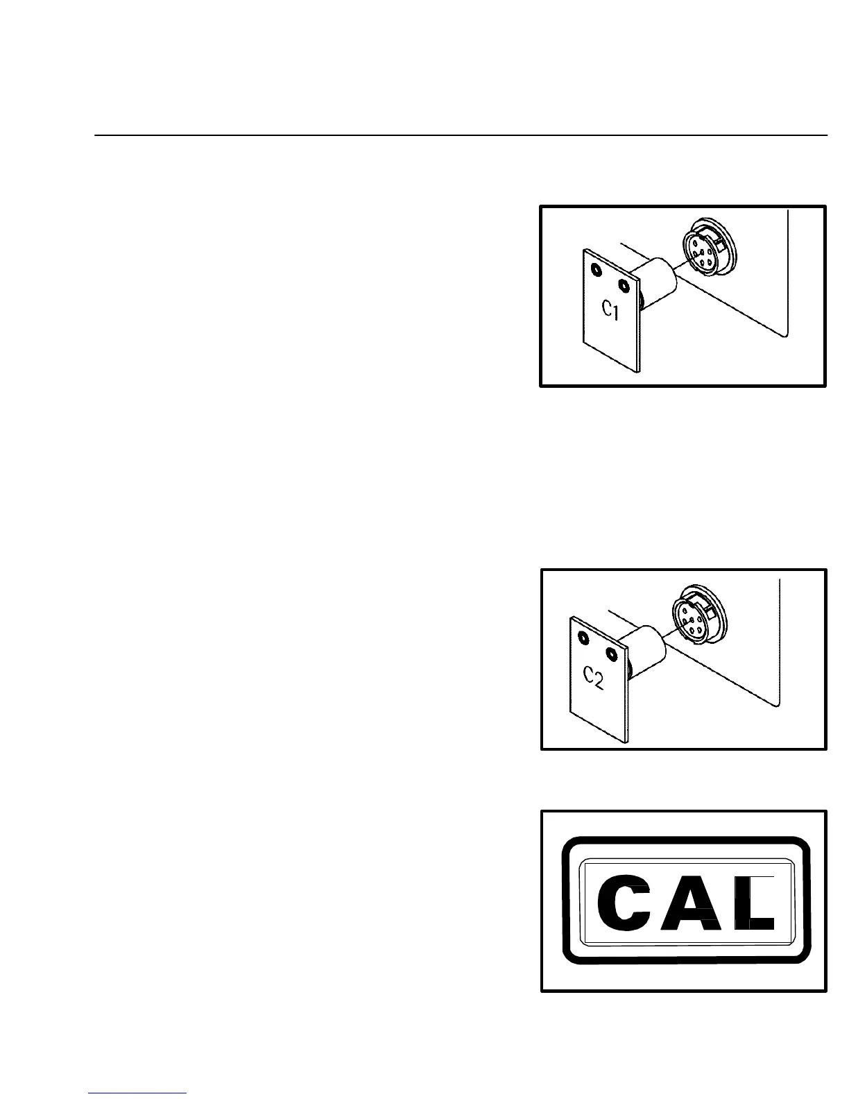
18. Disconnect the handpiece from the Current Channel’s
Power Output Receptacle and insert the "C-1" Calibration
Module.
DIGITAL READOUT ACCURACY
Figure 22. Insert "C-1" Module
19. Press and release the TIP SET Key. The Digital Readout will flash "- - -" to indicate that the system
microprocessor controlled temperature sensing and display circuitry is recalibrating one aspect of the
system circuitry. "C-2" will now be displayed.
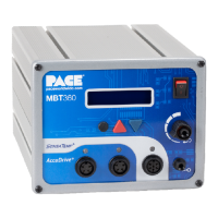
20. Remove the "C-1" Calibration Module and insert the "C-2"
Calibration Module.
Figure 23. Insert "C-2" Module
21. Press and release the TIP SET Key once again. The Digital
Readout will flash "- - -" to indicate that the system
microprocessor controlled temperature sensing and display
circuitry is recalibrating another aspect of the system.
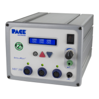
"CAL" will now be displayed, indicating that calibration of
this channel is complete.
Figure 24. Digital Readout "CAL"
41